3 of 42
TABLE
OF
CONTENTS
PAGE
1.0 GENERAL
SPECIFICATION ...................................................................... 4
2.0 TOOLS
REQUIRED
FOR INSTALLATION................................................. 5
3.0 CONTENTS ................................................................................................ 6
4.0 INSTALLATION INSTRUCTIONS .............................................................. 7
4.1 Chalk
Line Layout .................................................................... 9
4.2 Front And Rear Crossmember Assemblies ............................ 10
4.3 Power
Pack
Installation.......................................................... 14
4.4 Hydraulic
Installation .............................................................. 14
4.5 Electrical Connections ........................................................... 15
4.6 Cable
Installation ................................................................... 15
4.7 Air
Installations ...................................................................... 16
4.8 Anchor
Installation ................................................................. 17
4.9 Deck
Leveling Procedure ....................................................... 18
4.10 Final Check Of Assembled Lift ............................................. 20
4.11 Operation
Test With Vehicle ................................................ 21
5.0
SAFETY AND OPERATING INSTRUCTIONS ......................................... 22
6.0 SAFETY
AWARENESS ............................................................................ 23
7.0 RECOMMENDED
MAINTENANCE .......................................................... 24
8.0 PARTS
LIST ............................................................................................. 25
8.1 Lift
Assembly ......................................................................... 25
8.2 Parts List – Lift Assembly ...................................................... 26
8.3 Tower
Assembly .................................................................... 27
8.4 Parts List – Power Tower Assembly ...................................... 28
8.5 Deck Assembly (Left Side) ..................................................... 29
8.6 Parts List – Deck Assembly (Left Side) .................................. 30
8.7 Crossmember Assembly ........................................................ 31
8.8 Parts List – Crossmember Assembly ..................................... 32
8.9 Cylinder
Assembly ................................................................. 33
8.10 Parts List – Cylinder Assembly ............................................ 34
8.11 Hydraulic
And Air Kit ............................................................ 35
8.12 Parts List – Hydraulic And Air Kit ......................................... 36
8.13 Cable
Routing ...................................................................... 37
8.14 Parts List – Cable Routing ................................................... 38
8.15 Power
Pack
Assembly ......................................................... 39
8.16 Parts
List
– Power Pack ....................................................... 40
9.0 AVAILABLE
ACCESSORIES ................................................................... 42
Summary of Contents for ALIGNMENT EELR124A
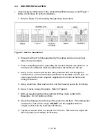
Page 8: ...8 of 42 TYPICAL BAY LAYOUT ...
Page 23: ...23 of 42 6 0 SAFETY AWARENESS AUTOMOTIVE LIFT INSTITUTE ALI ...
Page 25: ...25 of 42 8 0 PARTS LIST 8 1 LIFT ASSEMBLY ...
Page 27: ...27 of 42 8 3 TOWER ASSEMBLY ...
Page 29: ...29 of 42 8 5 DECK ASSEMBLY LEFT SIDE ...
Page 31: ...31 of 42 8 7 CROSSMEMBER ASSEMBLY ...
Page 33: ...33 of 42 8 9 CYLINDER ASSEMBLY ...
Page 35: ...35 of 42 8 11 HYDRAULIC AND AIR KIT ...
Page 37: ...37 of 42 8 13 CABLE ROUTING ...


