9 of 42
4.1
CHALK LINE LAYOUT
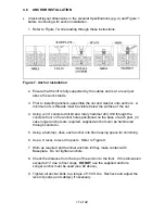
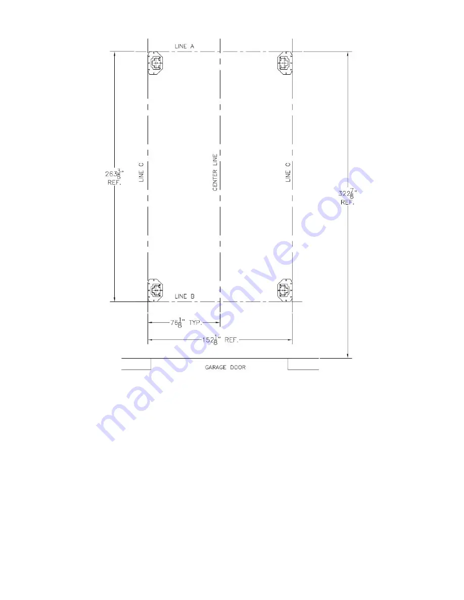
Figure 1. Chalk line layout
•
Refer to Figure 1.
Make a chalk line parallel to the doorway at least 322-7/8” in
from the doorway. This will be the location for the front face of the tower baseplate.
Call this line "A".
•
Determine the center of the doorway and bay. Make a centerline to intersect with line
"A".
•
Make a chalk line parallel to line “A”, 263-3/8” back toward the door. Call this line “B”.
•
Make two chalk lines spaced 76-1/8” to the left and right side of the centerline
intersecting line “A” and line ”B”. Call these lines, line “C”. These will be the lines that
the outside edge of the tower baseplate runs along.
Summary of Contents for ALIGNMENT EELR124A
Page 8: ...8 of 42 TYPICAL BAY LAYOUT ...
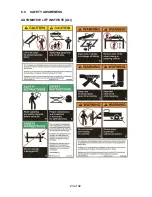
Page 23: ...23 of 42 6 0 SAFETY AWARENESS AUTOMOTIVE LIFT INSTITUTE ALI ...
Page 25: ...25 of 42 8 0 PARTS LIST 8 1 LIFT ASSEMBLY ...
Page 27: ...27 of 42 8 3 TOWER ASSEMBLY ...
Page 29: ...29 of 42 8 5 DECK ASSEMBLY LEFT SIDE ...
Page 31: ...31 of 42 8 7 CROSSMEMBER ASSEMBLY ...
Page 33: ...33 of 42 8 9 CYLINDER ASSEMBLY ...
Page 35: ...35 of 42 8 11 HYDRAULIC AND AIR KIT ...
Page 37: ...37 of 42 8 13 CABLE ROUTING ...


