8
Platform Notes: SPARCstation 10SX and SPARCstation 20 System Configuration Guide • February 2000
This layout results in one contiguous block of 256 MBytes (slots 0, 1, 2, and 3)
beginning at physical address 0, and another block of 192 MBytes (slots 4, 5, 6, and
7) beginning at physical address 0x14000000. Therefore, the maximum amount of
DRAM that can be installed in this configuration is 448 MBytes.
A typical system will most likely have 16 MByte and 64 MByte DSIMMs, and
VSIMMs. There are a large number of possible permutations of the system
configuration which, due to space limitations, will not be discussed here.
To be able to allocate the largest possible block of SXDRAM with a given set of
VSIMMs and DSIMMs, use the illustrations in this section as a guide.
The next section provides some information unique to the SPARCstation 20. The two
sections following that discuss system software constraints and configuration
recommendations that involve both systems.
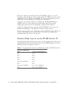
Memory Bank Layout on the SPARCstation 20
On the SPARCstation 20, the physical sequence of slots is different from that slots on
the SPARCstation 10SX. The slots that can be used for VSIMMs differ as well. The
different layouts are compared in
.
TABLE 2-4
Comparing Slot Locations on the SPARCstation 10SX and SPARCstation 20
Slot Names on SPARCstation
10SX
Slot Names on SPARCstation 20
Slot 7
Slot 0
Slot 3
Slot 2
Slot 6
Slot 5
Slot 2
Slot 3
Slot 5 (can be VSIMM 1)
Slot 6
Slot 1
Slot 1
Slot 4 (can be VSIMM 0)
Slot 7 (can be VSIMM 0)
Slot 0
Slot 4 (can be VSIMM 1)

