x
SPARCstation 4 Model 110 Service Manual • July 1996
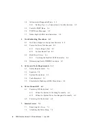
FIGURE 8-3
Power LED and Speaker/LED Board Cable Connectors
8-6
FIGURE 8-4
Positioning the LED Cable
8-7
FIGURE 8-5
Removing the Speaker Cover
8-9
FIGURE 8-6
Removing the Speaker
8-10
FIGURE 8-7
Speaker Connections
8-11
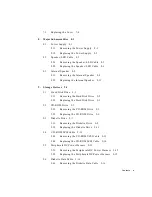
FIGURE 9-1
Drive Locations
9-2
FIGURE 9-2
Removing the Hard Disk Drive
9-3
FIGURE 9-3
Replacing the Disk Drive
9-4
FIGURE 9-4
Removing the CD-ROM Drive
9-5
FIGURE 9-5
Jumper Settings for the CD-ROM Drive
9-6
FIGURE 9-6
Replacing the CD-ROM Drive
9-7
FIGURE 9-7
Diskette Drive Location
9-8
FIGURE 9-8
Removing the CD-ROM Filler Panel
9-9
FIGURE 9-9
Disengaging the Diskette Drive
9-10
FIGURE 9-10
Removing the Diskette Drive
9-11
FIGURE 9-11
Replacing the Diskette Drive
9-12
FIGURE 9-12
System Board Cable Connections
9-13
FIGURE 9-13
Internal Cable Routing
9-14
FIGURE 9-14
Diskette Data Cable Routing
9-17
FIGURE 9-15
Audio Cable Connector on the CD-ROM Drive
9-18
FIGURE 9-16
Removing the Audio Cable From the Audio Module
9-19
FIGURE 9-17
Disconnecting the System Board Connectors
9-20
FIGURE 9-18
Pressing the Audio Cable Into the Cable Slot
9-21
FIGURE 9-19
Routing the Audio Cable Around the Corner Post
9-22
FIGURE 9-20
Securing the Audio Cable
9-23
FIGURE 9-21
CD-ROM Audio Cable Connector
9-23
FIGURE 9-22
Reconnecting the Main Logic Board Connectors
9-24
FIGURE 10-1
SPARCstation 4 System Board
10-2
Summary of Contents for SPARCstation 4 110
Page 24: ...1 6 SPARCstation 4 Model 110 Service Manual July 1996...
Page 36: ...2 12 SPARCstation 4 Model 110 Service Manual July 1996...
Page 46: ...3 10 SPARCstation 4 Model 110 Service Manual July 1996...
Page 108: ...10 4 SPARCstation 4 Model 110 Service Manual July 1996...
Page 146: ...12 6 SPARCstation 4 Model 110 Service Manual July 1996...
Page 150: ...A 4 SPARCstation 4 Model 110 Service Manual July 1996...
Page 160: ...B 10 SPARCstation 4 Model 110 Service Manual July 1996...
Page 174: ...Glossary 4 SPARCstation 4 Model 110 Service Manual July 1996...

