xii
SPARCstation 4 Model 110 Service Manual • July 1996
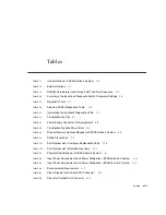
FIGURE 11-29
Removing the System Board
11-26
FIGURE 11-30
Installing the System Board
11-27
FIGURE 11-31
System Board Captive Screws
11-28
FIGURE 11-32
Setting the Serial Port Jumpers
11-29
FIGURE 11-33
Locating the NVRAM Chip
11-31
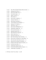
FIGURE 12-1
Selected CRUs—System Unit
12-2
FIGURE 12-2
Standard External Cables
12-3
FIGURE 12-3
Optional External Cable
12-3
FIGURE 12-4
Microphone and Cable
12-4
FIGURE B-1
External SCSI Connector
B-1
FIGURE B-2
Parallel Port Connector
B-2
FIGURE B-3
Attachment Unit Interface (AUI) Connector
B-3
FIGURE B-4
Twisted-Pair Ethernet Connector
B-4
FIGURE B-5
Serial Connector
B-4
FIGURE B-6
Keyboard/Mouse Connector
B-5
FIGURE B-7
Audio Module Connectors
B-6
FIGURE B-8
Headphone Connector
B-6
FIGURE B-9
Audio Line-out Connector
B-7
FIGURE B-10
Audio Line-in Connector
B-7
FIGURE B-11
Microphone Connector
B-7
FIGURE B-12
13W3 Video Connector
B-9
Summary of Contents for SPARCstation 4 110
Page 24: ...1 6 SPARCstation 4 Model 110 Service Manual July 1996...
Page 36: ...2 12 SPARCstation 4 Model 110 Service Manual July 1996...
Page 46: ...3 10 SPARCstation 4 Model 110 Service Manual July 1996...
Page 108: ...10 4 SPARCstation 4 Model 110 Service Manual July 1996...
Page 146: ...12 6 SPARCstation 4 Model 110 Service Manual July 1996...
Page 150: ...A 4 SPARCstation 4 Model 110 Service Manual July 1996...
Page 160: ...B 10 SPARCstation 4 Model 110 Service Manual July 1996...
Page 174: ...Glossary 4 SPARCstation 4 Model 110 Service Manual July 1996...

