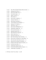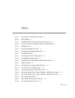
Tables
xiii
Tables
TABLE 1-1
Internal Options—SPARCstation 4 System
1-4
TABLE 1-2
External Options
1-5
TABLE 2-1
NVRAM Parameters Used During POST and Boot Sequence
2-5
TABLE 2-2
Summary of Autoboot and Diagnostic Switch Parameter Settings
2-6
TABLE 2-3
Diagnostic Tools
2-7
TABLE 2-4
Selected FORTH Diagnostic Tests
2-8
TABLE 3-1
Interpreting the Keyboard Diagnostic LEDs
3-3
TABLE 4-1
Troubleshooting Tips
4-1
TABLE 4-2
Power Supply Connector Pin Assignments
4-4
TABLE 4-3
Troubleshooting Disk Drive Errors
4-6
TABLE 4-4
Physical Memory Address Ranges for SPARCstation 4 System
4-8
TABLE 5-1
Safety Precautions
5-2
TABLE 12-1
Part Number List—Customer-Replaceable Units
12-4
TABLE 12-2
Part Number List—Miscellaneous Items
12-5
TABLE A-1
Physical Specifications—SPARCstation 4 System
A-1
TABLE A-2
Input Power Requirements and Power Dissipation—SPARCstation 4 System
A-2
TABLE A-3
Input Power Requirements and Power Dissipation—SPARCserver 4 System
A-2
TABLE A-4
Environmental Requirements
A-3
TABLE B-1
Pinout Signals for External SCSI Connector
B-1
TABLE B-2
Pinout for Parallel Port Connector
B-2
Summary of Contents for SPARCstation 4 110
Page 24: ...1 6 SPARCstation 4 Model 110 Service Manual July 1996...
Page 36: ...2 12 SPARCstation 4 Model 110 Service Manual July 1996...
Page 46: ...3 10 SPARCstation 4 Model 110 Service Manual July 1996...
Page 108: ...10 4 SPARCstation 4 Model 110 Service Manual July 1996...
Page 146: ...12 6 SPARCstation 4 Model 110 Service Manual July 1996...
Page 150: ...A 4 SPARCstation 4 Model 110 Service Manual July 1996...
Page 160: ...B 10 SPARCstation 4 Model 110 Service Manual July 1996...
Page 174: ...Glossary 4 SPARCstation 4 Model 110 Service Manual July 1996...

