Chapter 11
System Board and Component Replacement
11-23
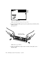
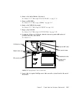
FIGURE 11-25
Orienting the VSIMM
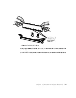
4. Place your thumbs as shown in
FIGURE 11-26
and push the VSIMM firmly into its
connector.
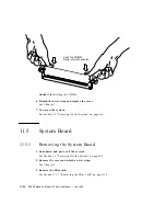
5. To lock the VSIMM in place, push both ejector levers into the upright position.
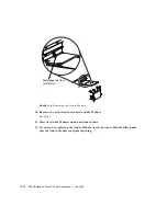
Align notches with
corresponding
tabs in VSIMM
connector.
Summary of Contents for SPARCstation 4 110
Page 24: ...1 6 SPARCstation 4 Model 110 Service Manual July 1996...
Page 36: ...2 12 SPARCstation 4 Model 110 Service Manual July 1996...
Page 46: ...3 10 SPARCstation 4 Model 110 Service Manual July 1996...
Page 108: ...10 4 SPARCstation 4 Model 110 Service Manual July 1996...
Page 146: ...12 6 SPARCstation 4 Model 110 Service Manual July 1996...
Page 150: ...A 4 SPARCstation 4 Model 110 Service Manual July 1996...
Page 160: ...B 10 SPARCstation 4 Model 110 Service Manual July 1996...
Page 174: ...Glossary 4 SPARCstation 4 Model 110 Service Manual July 1996...


