Chapter 11
System Board and Component Replacement
11-25
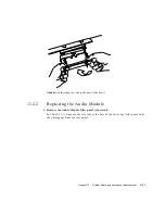
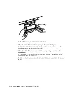
4. Remove the Audio Module (if present).
See Section 11.2.1 “Removing the Audio Module” on page 11-8.
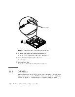
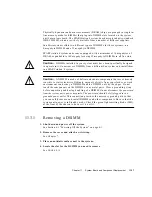
5. Remove all DSIMMs.
See Section 11.3.1 “Removing a DSIMM” on page 11-17.
6. Remove the VSIMM (if present).
See Section 11.4.1 “Removing the VSIMM” on page 11-20.
7. Remove the NVRAM.
See Section 11.6.1 “Removing the NVRAM Chip” on page 11-30.
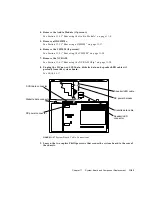
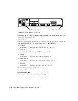
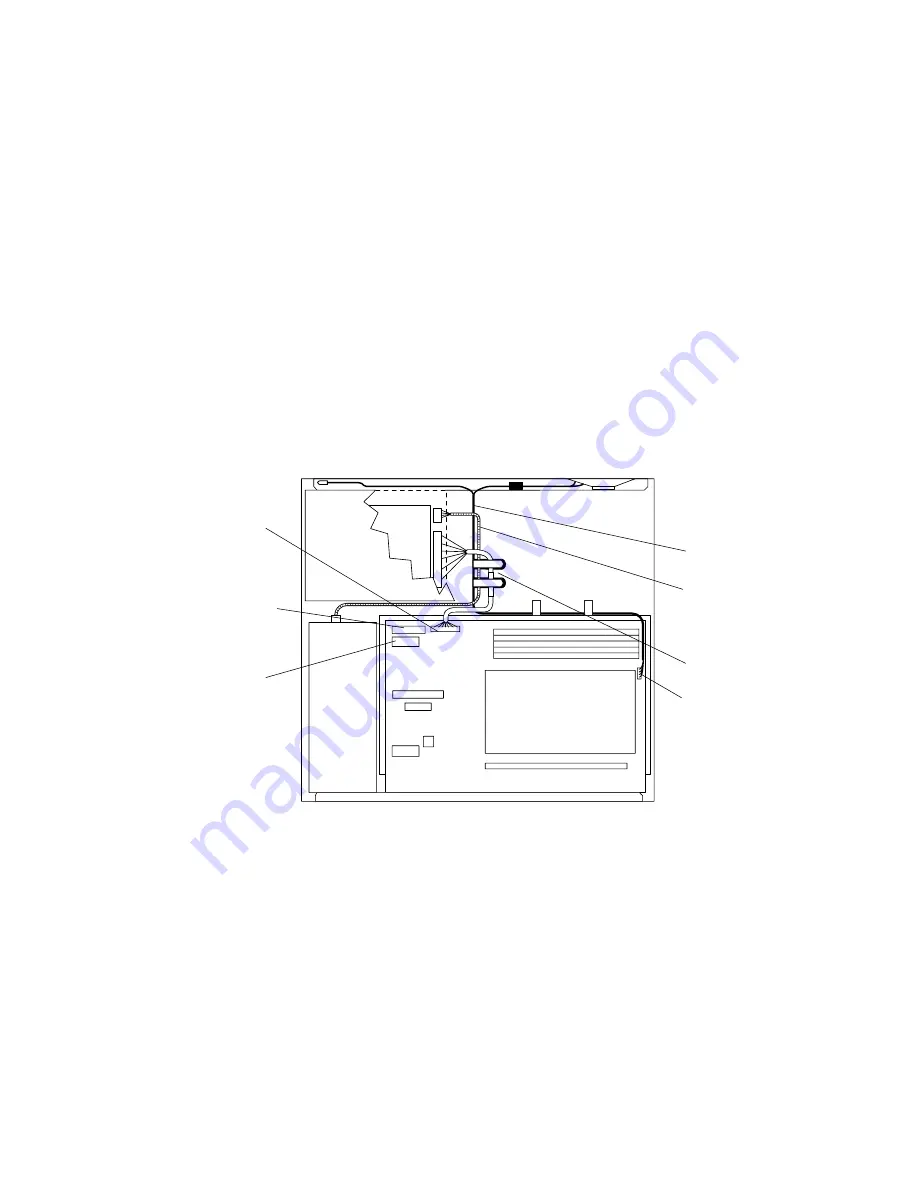
8. Unplug the DC power, SCSI data, diskette data, and speaker/LED cables (if
present) from the system board.
See
FIGURE 11-27
.
FIGURE 11-27
System Board Cable Connections
9. Loosen the two captive Phillips screws that secure the system board to the rear of
the chassis.
Speaker/LED
Diskette data connector
connector
SCSI data connector
DC power connector
Speaker/LED cable
Diskette data cable
DC power harness
Summary of Contents for SPARCstation 4 110
Page 24: ...1 6 SPARCstation 4 Model 110 Service Manual July 1996...
Page 36: ...2 12 SPARCstation 4 Model 110 Service Manual July 1996...
Page 46: ...3 10 SPARCstation 4 Model 110 Service Manual July 1996...
Page 108: ...10 4 SPARCstation 4 Model 110 Service Manual July 1996...
Page 146: ...12 6 SPARCstation 4 Model 110 Service Manual July 1996...
Page 150: ...A 4 SPARCstation 4 Model 110 Service Manual July 1996...
Page 160: ...B 10 SPARCstation 4 Model 110 Service Manual July 1996...
Page 174: ...Glossary 4 SPARCstation 4 Model 110 Service Manual July 1996...

