11-26
SPARCstation 4 Model 110 Service Manual • July 1996
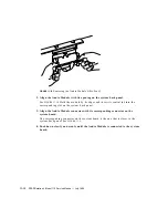
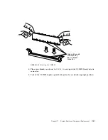
FIGURE 11-28
System Board Captive Screws
10. Pull the board out of the back of the chassis until it clears the plastic card guide.
11. Place the board on an antistatic surface.
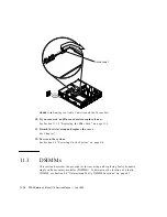
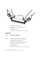
FIGURE 11-29
Removing the System Board
11.5.2
Replacing the System Board
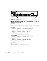
The serial port jumpers are preset for RS423 mode. See Section 11.5.3 “Setting
Jumpers” on page 11-29, if you need to change the jumpers on the system board to
RS232.
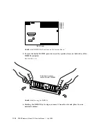
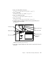
1. Install the new system board.
See
FIGURE 11-30
.
SERIAL A/B
TP
//
Loosen captive screw.
Loosen captive screw.
Card guide
System board
Summary of Contents for SPARCstation 4 110
Page 24: ...1 6 SPARCstation 4 Model 110 Service Manual July 1996...
Page 36: ...2 12 SPARCstation 4 Model 110 Service Manual July 1996...
Page 46: ...3 10 SPARCstation 4 Model 110 Service Manual July 1996...
Page 108: ...10 4 SPARCstation 4 Model 110 Service Manual July 1996...
Page 146: ...12 6 SPARCstation 4 Model 110 Service Manual July 1996...
Page 150: ...A 4 SPARCstation 4 Model 110 Service Manual July 1996...
Page 160: ...B 10 SPARCstation 4 Model 110 Service Manual July 1996...
Page 174: ...Glossary 4 SPARCstation 4 Model 110 Service Manual July 1996...

