B-6
SPARCstation 4 Model 110 Service Manual • July 1996
Note –
All signals are standard TTL levels. The +5V supply is fuse-protected.
B.7
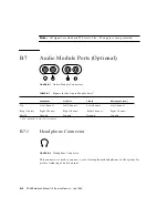
Audio Module Ports (Optional)
FIGURE B-7
Audio Module Connectors
B.7.1
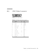
Headphone Connector
FIGURE B-8
Headphone Connector
This connector is used to connect a set of stereophonic headphones to the system for
private listening of audio output.
TABLE B-7
Signals for the Audio Module Ports
1
1. E.I.A. standard 3.5-mm/0.125-inch jacks.
Headphone
Line-Out
Line-In
Microphone (new)
Tip
Left Channel
Left Channel
Left Channel
Left Channel
Ring (Center)
Right Channel
Right Channel
Right Channel
Right Channel
Shield
Ground
Ground
Ground
Ground
Summary of Contents for SPARCstation 4 110
Page 24: ...1 6 SPARCstation 4 Model 110 Service Manual July 1996...
Page 36: ...2 12 SPARCstation 4 Model 110 Service Manual July 1996...
Page 46: ...3 10 SPARCstation 4 Model 110 Service Manual July 1996...
Page 108: ...10 4 SPARCstation 4 Model 110 Service Manual July 1996...
Page 146: ...12 6 SPARCstation 4 Model 110 Service Manual July 1996...
Page 150: ...A 4 SPARCstation 4 Model 110 Service Manual July 1996...
Page 160: ...B 10 SPARCstation 4 Model 110 Service Manual July 1996...
Page 174: ...Glossary 4 SPARCstation 4 Model 110 Service Manual July 1996...


