4-4
SPARCstation 4 Model 110 Service Manual • July 1996
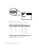
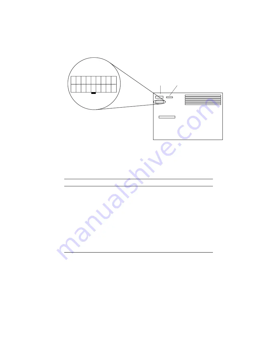
FIGURE 4-1
Power Supply Connector
TABLE 4-2
shows the pin assignments on the power supply connector.
TABLE 4-2
Power Supply Connector Pin Assignments
Pin
Color
Description
1
1. All volts are direct current.
Pin
Color
Description
1
Blue
+12V
10
Black
Ground
2
Brown
-12V
11
Black
Ground
3
Red
+5V
12
Black
Ground2
4
Red
+5V
13
Black
Ground2
5
Red
+5V
2
2. The SPARCstation 4
power supply
has
no connections to pins 5, 6, 12, 13, and 16.
The SPARCserver 4 power supply has connections to all pins.
14
Black
Ground
6
Red
+5V2
15
Black
Ground
7
Red
+5V
16
Green
AC Outlet2
8
Red
+5V
17
Purple
Fan
9
Grey
Power off
18
Yellow
Power on
1
9
10
18
2
11
13 14
16
12
15
17
3 4 5 6
8
7
Release clip
Floppy SCSI
Summary of Contents for SPARCstation 4 110
Page 24: ...1 6 SPARCstation 4 Model 110 Service Manual July 1996...
Page 36: ...2 12 SPARCstation 4 Model 110 Service Manual July 1996...
Page 46: ...3 10 SPARCstation 4 Model 110 Service Manual July 1996...
Page 108: ...10 4 SPARCstation 4 Model 110 Service Manual July 1996...
Page 146: ...12 6 SPARCstation 4 Model 110 Service Manual July 1996...
Page 150: ...A 4 SPARCstation 4 Model 110 Service Manual July 1996...
Page 160: ...B 10 SPARCstation 4 Model 110 Service Manual July 1996...
Page 174: ...Glossary 4 SPARCstation 4 Model 110 Service Manual July 1996...


