System Board and Component Replacement
11-13
11
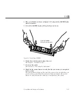
11.3 DSIMMs
This section describes the procedures for removing and replacing faulty
DSIMMs. To determine the location of a faulty DSIMM, see Section 4.4,
“Determining Faulty DSIMM Locations.”
SPARCstation 5 system units come equipped with a minimum of 16 Mbytes of
dynamic random access memory (DRAM), expandable to 256 Mbytes.
Physically, DRAM chips are grouped in single in-line memory modules
(DSIMMs) that plug in to each of the eight DSIMM slots located on the system
unit’s main logic board.
The SPARCstation 5 system accepts industry-standard JEDEC SIMMs, which
are widely available from a number of different suppliers. Sun Microsystems
offers two different types of DSIMMs for this system—an 8-Mbyte DSIMM and
a 32-Mbyte DSIMM. The maximum memory configuration is 256 Mbytes using
eight 32-Mbyte DSIMMs.
Caution –
DSIMMs installed in your system must have been specifically
designed to operate in it. Do not remove DSIMMs from a different Sun system
and install them in a SPARCstation 5 system.
Caution –
A DSIMM is made of delicate electronic components that are
extremely sensitive to static electricity. Ordinary amounts of static from your
clothes or work environment can destroy a DSIMM. Handle a DSIMM only by
the edges. Do not touch the components on the DSIMM or any metal parts.
Wear a grounding strap before unpacking and during handling of a DSIMM.
Do not disconnect the power cord from the system unit’s power receptacle. The power
cord should be left plugged in to a grounded power outlet. This connection provides
the ground path necessary so that you can safely remove and install DSIMMs
and other components.
Be sure that the system unit power is in Standby mode. Check the green light-
emitting diode (LED) at the front of the chassis to be sure it is not lit.
!
!
Summary of Contents for SPARCstation 5
Page 12: ...x SPARCstation 5 Service Manual November 1996...
Page 22: ...xx SPARCstation 5 Service Manual November 1996...
Page 23: ...Part 1 SystemInformation Chapter 1 Product Description...
Page 24: ......
Page 32: ......
Page 44: ...2 12 SPARCstation 5 Service Manual November 1996 2...
Page 64: ...4 10 SPARCstation 5 Service Manual November 1996 4...
Page 65: ...Part 3 PreparingforService Chapter 5 Safety and Tools Requirements Chapter 6 Power On and Off...
Page 66: ......
Page 72: ...5 6 SPARCstation 5 Service Manual November 1996 5...
Page 78: ......
Page 130: ...9 32 SPARCstation 5 Service Manual November 1996 9...
Page 132: ......
Page 136: ...10 4 SPARCstation 5 Service Manual November 1996 10...
Page 162: ...11 26 SPARCstation 5 Service Manual November 1996 11...
Page 163: ...Part 6 IllustratedPartsBreakdown Chapter 12 Illustrated Parts Breakdown...
Page 164: ......
Page 172: ......
Page 176: ...A 4 SPARCstation 5 Service Manual November 1996 A...
Page 198: ...D 10 SPARCstation 5 Service Manual November 1996 D...
Page 208: ...SPARCstation 5 Service Manual November 1996...
Page 210: ......

