System Board and Component Replacement
11-17
11
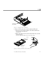
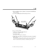
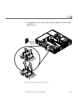
4. Place your thumbs as shown in Figure 11-17 and push the DSIMM firmly
into its connector.
5. To lock the DSIMM in place, lift up both ejector levers.
Figure 11-17 Installing a DSIMM
6. Detach the wrist strap and replace the cover.
See Chapter 7, “Internal Access.”
7. Power on the system.
See Section 6.2, “Powering On the System.”
8. Watch for the system banner to verify that the new memory is recognized
by the system.
The system banner appears at the top of the screen a few seconds after you
power on the system. Check the amount of memory listed in the system
banner to verify that the new memory is recognized by the system.
Push the DSIMM
firmly into its connector.
Summary of Contents for SPARCstation 5
Page 12: ...x SPARCstation 5 Service Manual November 1996...
Page 22: ...xx SPARCstation 5 Service Manual November 1996...
Page 23: ...Part 1 SystemInformation Chapter 1 Product Description...
Page 24: ......
Page 32: ......
Page 44: ...2 12 SPARCstation 5 Service Manual November 1996 2...
Page 64: ...4 10 SPARCstation 5 Service Manual November 1996 4...
Page 65: ...Part 3 PreparingforService Chapter 5 Safety and Tools Requirements Chapter 6 Power On and Off...
Page 66: ......
Page 72: ...5 6 SPARCstation 5 Service Manual November 1996 5...
Page 78: ......
Page 130: ...9 32 SPARCstation 5 Service Manual November 1996 9...
Page 132: ......
Page 136: ...10 4 SPARCstation 5 Service Manual November 1996 10...
Page 162: ...11 26 SPARCstation 5 Service Manual November 1996 11...
Page 163: ...Part 6 IllustratedPartsBreakdown Chapter 12 Illustrated Parts Breakdown...
Page 164: ......
Page 172: ......
Page 176: ...A 4 SPARCstation 5 Service Manual November 1996 A...
Page 198: ...D 10 SPARCstation 5 Service Manual November 1996 D...
Page 208: ...SPARCstation 5 Service Manual November 1996...
Page 210: ......

