B-10
SPARCstation 5 Service Manual—November 1996
B
B.8 13W3 Video Connector
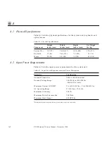
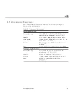
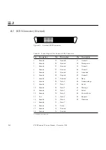
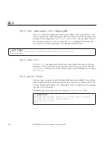
Figure B-8 shows a 13W3 video connector. The 13W3 connector’s pin
assignments and functions are described in Table B-8. The connector is built
into the SBus or S24 frame buffer card.
Figure B-8
13W3 Video Connector
Table B-8 13W3 Video Connector Pin Assignments
Pin
Function
I/O
Level
A1
Red
O
Analog
A2
Green
O
Analog
A3
Blue
O
Analog
1
Serial Read
TTL
2
Vert Sync
O
TTL
3
Sense <0>
I
TTL
4
Ground
GND
5
Comp Sync
O
TTL
6
Hort Sync
O
TTL
7
Serial Write
TTL
8
Sense <1>
I
TTL
9
Sense <2>
I
TTL
10
Ground
GND
A1
A2
A3
1
5
6
10
Summary of Contents for SPARCstation 5
Page 12: ...x SPARCstation 5 Service Manual November 1996...
Page 22: ...xx SPARCstation 5 Service Manual November 1996...
Page 23: ...Part 1 SystemInformation Chapter 1 Product Description...
Page 24: ......
Page 32: ......
Page 44: ...2 12 SPARCstation 5 Service Manual November 1996 2...
Page 64: ...4 10 SPARCstation 5 Service Manual November 1996 4...
Page 65: ...Part 3 PreparingforService Chapter 5 Safety and Tools Requirements Chapter 6 Power On and Off...
Page 66: ......
Page 72: ...5 6 SPARCstation 5 Service Manual November 1996 5...
Page 78: ......
Page 130: ...9 32 SPARCstation 5 Service Manual November 1996 9...
Page 132: ......
Page 136: ...10 4 SPARCstation 5 Service Manual November 1996 10...
Page 162: ...11 26 SPARCstation 5 Service Manual November 1996 11...
Page 163: ...Part 6 IllustratedPartsBreakdown Chapter 12 Illustrated Parts Breakdown...
Page 164: ......
Page 172: ......
Page 176: ...A 4 SPARCstation 5 Service Manual November 1996 A...
Page 198: ...D 10 SPARCstation 5 Service Manual November 1996 D...
Page 208: ...SPARCstation 5 Service Manual November 1996...
Page 210: ......


