2-4
SPARCstation 5 Service Manual—November 1996
2
2.2 After Power Is Switched On
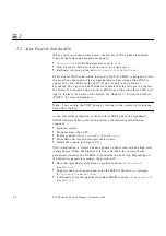
When you turn on the system power, the low-level POST phase is initiated
if any of the following circumstances apply:
•
diag-switch?
NVRAM parameter is set to
true
.
•
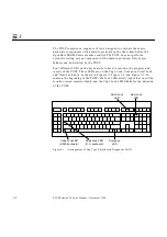
Stop-d keys are held down when you turn on the power.
•
Keyboard is disconnected, and
diag-switch?
is set to
false
.
The low-level POST code, which is stored in the boot PROM, is designed to test
the most basic functions of the system hardware. The status of the POST is
conveyed by four LEDs on the Sun™ Type-4, Type-5, and Compact 1
keyboards. The Caps Lock LED blinks to indicate that the tests are in progress.
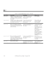
If a failure is detected during low-level POST, one of the other three LEDs will
light to indicate the nature of the failure. See Chapter 3, “Power-On Self-Test
(POST),” for more information.
Note –
You can skip the POST phase by turning on the system while holding
down the Stop key.
At the successful completion of the low-level POST phase, the OpenBoot
PROM firmware takes control and performs the following initialization
sequence:
•
Initialize system
•
Probe memory, then CPU
•
Evaluate Script (if
use-nvramrc?
is set to
true
)
•
Probe SBus devices and interpret their drivers
•
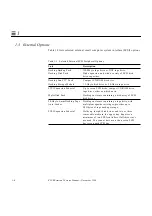
Install the console (see Figure 2-2)
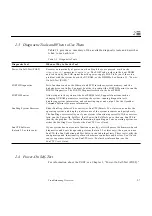
After initialization, a system banner appears on the screen, and the high-level
testing begins. When the high-level tests are finished, the system checks
parameters stored in the NVRAM to determine the next step. Depending on
the following parameter settings, the system will:
•
Boot the operating system from a specified location, if
auto-boot?
is set to
true
•
Suppress the boot sequence and enter the FORTH Monitor (
ok
prompt),
if
auto-boot?
is set to
false
•
Continually cycle through the OpenBoot PROM sequence, if
mfg-switch?
is set to
true
Summary of Contents for SPARCstation 5
Page 12: ...x SPARCstation 5 Service Manual November 1996...
Page 22: ...xx SPARCstation 5 Service Manual November 1996...
Page 23: ...Part 1 SystemInformation Chapter 1 Product Description...
Page 24: ......
Page 32: ......
Page 44: ...2 12 SPARCstation 5 Service Manual November 1996 2...
Page 64: ...4 10 SPARCstation 5 Service Manual November 1996 4...
Page 65: ...Part 3 PreparingforService Chapter 5 Safety and Tools Requirements Chapter 6 Power On and Off...
Page 66: ......
Page 72: ...5 6 SPARCstation 5 Service Manual November 1996 5...
Page 78: ......
Page 130: ...9 32 SPARCstation 5 Service Manual November 1996 9...
Page 132: ......
Page 136: ...10 4 SPARCstation 5 Service Manual November 1996 10...
Page 162: ...11 26 SPARCstation 5 Service Manual November 1996 11...
Page 163: ...Part 6 IllustratedPartsBreakdown Chapter 12 Illustrated Parts Breakdown...
Page 164: ......
Page 172: ......
Page 176: ...A 4 SPARCstation 5 Service Manual November 1996 A...
Page 198: ...D 10 SPARCstation 5 Service Manual November 1996 D...
Page 208: ...SPARCstation 5 Service Manual November 1996...
Page 210: ......


