Power-On Self-Test (POST)
3-5
3
You can retrieve more detailed POST failure information by connecting a
terminal to the
ttya
serial port. If you connect a terminal, you must set the
NVRAM parameter
diag-switch?
to
true
. For more information about the
NVRAM parameters, see Table 2-1. Test failure messages are displayed on the
system monitor or console, whether or not the system is in Diagnostic Mode.
However, it may be easier to understand the failure message output when it is
accompanied by more detailed POST progress messages available via the
ttya
serial port.
3.2 Normal Mode
Under Normal Mode, when the system is turned on, control is sent to the
OpenBoot PROM. Depending on the options set in the OpenBoot PROM,
for example if
auto-boot?
is enabled (set to
true
), the operating system
will load. Diagnostic testing is not run.
3.3 Full Diagnostic Mode
Full Diagnostic Mode tests the major hardware system board components and,
if the POST is successful, control is transferred to the OBP firmware that probes
the installed SBus modules. Full Diagnostic Mode runs if one of these
conditions is met:
•
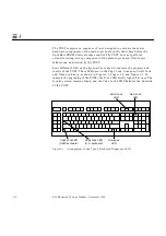
You press and hold the Stop-d keys while you turn on the power.
•
You set the
diag-switch?
NVRAM parameter to
true
in the OpenBoot
PROM.
•
You disconnect the keyboard and you set the
diag-switch?
NVRAM
parameter to
true
in the OpenBoot PROM.
Note –
POST does not perform extensive testing on any system board
component. POST detects only major failures.
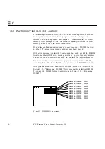
To view error messages returned by POST, connect a terminal to serial port A
or use a
tip
connection to another workstation.
If you do not connect a terminal to serial port A or use a
tip
connection,
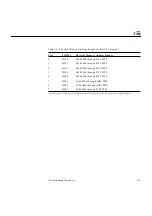
the screen will be blank during the POST diagnostics. In this case, use the
keyboard LEDs to display error conditions. See Section 3.7, “Status Lights
(LEDs) and Indicators.”
Summary of Contents for SPARCstation 5
Page 12: ...x SPARCstation 5 Service Manual November 1996...
Page 22: ...xx SPARCstation 5 Service Manual November 1996...
Page 23: ...Part 1 SystemInformation Chapter 1 Product Description...
Page 24: ......
Page 32: ......
Page 44: ...2 12 SPARCstation 5 Service Manual November 1996 2...
Page 64: ...4 10 SPARCstation 5 Service Manual November 1996 4...
Page 65: ...Part 3 PreparingforService Chapter 5 Safety and Tools Requirements Chapter 6 Power On and Off...
Page 66: ......
Page 72: ...5 6 SPARCstation 5 Service Manual November 1996 5...
Page 78: ......
Page 130: ...9 32 SPARCstation 5 Service Manual November 1996 9...
Page 132: ......
Page 136: ...10 4 SPARCstation 5 Service Manual November 1996 10...
Page 162: ...11 26 SPARCstation 5 Service Manual November 1996 11...
Page 163: ...Part 6 IllustratedPartsBreakdown Chapter 12 Illustrated Parts Breakdown...
Page 164: ......
Page 172: ......
Page 176: ...A 4 SPARCstation 5 Service Manual November 1996 A...
Page 198: ...D 10 SPARCstation 5 Service Manual November 1996 D...
Page 208: ...SPARCstation 5 Service Manual November 1996...
Page 210: ......


