Troubleshooting Procedures
4-5
4
4.2.2 System Board Test
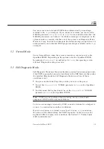
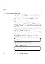
1. Connect a terminal to serial port A or use a
tip
connection to another
workstation to receive additional POST failure information.
To set up a
tip
connection to another workstation, see Section 3.4.1,
“Setting Up a tip Connection to Another System.”
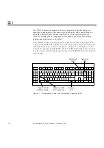
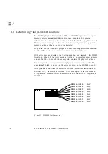
2. Press and hold the Stop-d keys. While holding the keys down, turn the
system power switch on. Watch the keyboard LEDs.
a. The Caps Lock key on the keyboard should flash on and off, indicating
that the system is running the Power-On Self-Test (POST).
If the Caps Lock key fails to flash on and off after you have pressed and
held the Stop-d keys, POST failed.
b. To further troubleshoot the system board, see Section 4.2.2.1, “Caps
Lock Key Fails to Flash On and Off During POST.”
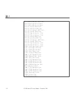
3. Observe the keyboard LEDs.
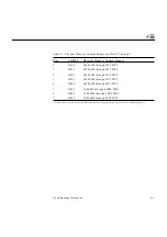
If a failure occurs during POST, an LED may light up. See Table 3-1 on
page 3-4 to interpret the keyboard diagnostic LEDs.
4. Replace the defective part indicated.
1. All volts are direct current.
Table 4-2
Power Supply Connector Pin Assignments
Pin
Color
Description
1
Pin
Color
Description
1
Blue
+12V
10
Black
Ground
2
Brown
-12V
11
Black
Ground
3
Red
+5V
12
Black
Ground
4
Red
+5V
13
Black
Ground
5
Red
+5V
14
Black
Ground
6
Red
+5V
15
Black
Ground
7
Red
+5V
16
Green
AC Outlet
8
Red
+5V
17
Purple
Fan
9
Grey
Power off
18
Yellow
Power on
Summary of Contents for SPARCstation 5
Page 12: ...x SPARCstation 5 Service Manual November 1996...
Page 22: ...xx SPARCstation 5 Service Manual November 1996...
Page 23: ...Part 1 SystemInformation Chapter 1 Product Description...
Page 24: ......
Page 32: ......
Page 44: ...2 12 SPARCstation 5 Service Manual November 1996 2...
Page 64: ...4 10 SPARCstation 5 Service Manual November 1996 4...
Page 65: ...Part 3 PreparingforService Chapter 5 Safety and Tools Requirements Chapter 6 Power On and Off...
Page 66: ......
Page 72: ...5 6 SPARCstation 5 Service Manual November 1996 5...
Page 78: ......
Page 130: ...9 32 SPARCstation 5 Service Manual November 1996 9...
Page 132: ......
Page 136: ...10 4 SPARCstation 5 Service Manual November 1996 10...
Page 162: ...11 26 SPARCstation 5 Service Manual November 1996 11...
Page 163: ...Part 6 IllustratedPartsBreakdown Chapter 12 Illustrated Parts Breakdown...
Page 164: ......
Page 172: ......
Page 176: ...A 4 SPARCstation 5 Service Manual November 1996 A...
Page 198: ...D 10 SPARCstation 5 Service Manual November 1996 D...
Page 208: ...SPARCstation 5 Service Manual November 1996...
Page 210: ......


