7-1
Internal Access
7
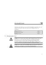
This chapter describes how to access the subassemblies inside the system unit,
and how to close the system unit after you have finished the service
procedures.
7.1 Removing the Cover
Caution –
The AC power cord should remain attached between the system
unit and an AC wall outlet. This connection provides the ground path
necessary to protect internal system components from harmful static
discharges. Inside the system unit, be sure that the power supply wiring
harness is connected to the main logic board to complete the ground.
Caution –
The surface of the TurboSPARC chip may be hot and could cause
personal injury if touched. Avoid contacting this component.
Removing the Cover
page 7-1
Attaching the Wrist Strap
page 7-4
Replacing the Cover
page 7-5
!
Summary of Contents for SPARCstation 5
Page 12: ...x SPARCstation 5 Service Manual November 1996...
Page 22: ...xx SPARCstation 5 Service Manual November 1996...
Page 23: ...Part 1 SystemInformation Chapter 1 Product Description...
Page 24: ......
Page 32: ......
Page 44: ...2 12 SPARCstation 5 Service Manual November 1996 2...
Page 64: ...4 10 SPARCstation 5 Service Manual November 1996 4...
Page 65: ...Part 3 PreparingforService Chapter 5 Safety and Tools Requirements Chapter 6 Power On and Off...
Page 66: ......
Page 72: ...5 6 SPARCstation 5 Service Manual November 1996 5...
Page 78: ......
Page 130: ...9 32 SPARCstation 5 Service Manual November 1996 9...
Page 132: ......
Page 136: ...10 4 SPARCstation 5 Service Manual November 1996 10...
Page 162: ...11 26 SPARCstation 5 Service Manual November 1996 11...
Page 163: ...Part 6 IllustratedPartsBreakdown Chapter 12 Illustrated Parts Breakdown...
Page 164: ......
Page 172: ......
Page 176: ...A 4 SPARCstation 5 Service Manual November 1996 A...
Page 198: ...D 10 SPARCstation 5 Service Manual November 1996 D...
Page 208: ...SPARCstation 5 Service Manual November 1996...
Page 210: ......

