Chapter 8
Major Subassemblies
79
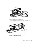
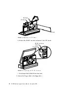
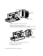
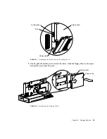
a. Unlock the connector locking device.
See
FIGURE 8-14
. Use the tip of a flat blade screwdriver or similar tool to push both
ends of the locking device away from the drive.
FIGURE 8-14
Unlocking the Floppy Connector
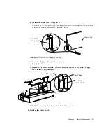
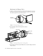
b. Insert the floppy cable into the connector.
See
FIGURE 8-15
.
c. Push down both sides of the connector locking device to secure the floppy
cable in the floppy connector.
FIGURE 8-15
Connecting the Floppy Cable to the Floppy Drive
4. Replace the video board.
Floppy drive
Connector
locking device
Floppy drive
Connector
locking device
Floppy cable
Summary of Contents for SPARCstation Voyager
Page 9: ...Contents ix test memory 146 power off 147 Glossary 149...
Page 10: ...x SPARCstation Voyager Service Manual December 1994...
Page 16: ...xvi SPARCstation Voyager Service Manual December 1994...
Page 22: ...xxii SPARCstation Voyager Service Manual December 1994...
Page 28: ...6 SPARCstation Voyager Service Manual December 1994...
Page 36: ...14 SPARCstation Voyager Service Manual December 1994...
Page 46: ...24 SPARCstation Voyager Service Manual December 1994...
Page 88: ...66 SPARCstation Voyager Service Manual December 1994...
Page 108: ...86 SPARCstation Voyager Service Manual December 1994...
Page 142: ...120 SPARCstation Voyager Service Manual December 1994...
Page 170: ...148 SPARCstation Voyager Service Manual December 1994...
Page 178: ...156 SPARCstation Voyager Service Manual December 1994...


