background image

48

SPARCstation Voyager Service Manual • December 1994

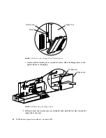
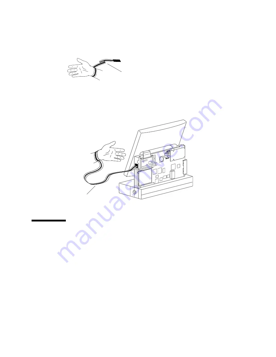
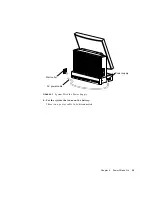
FIGURE 7-7

Wrapping the Wrist Strap Around Your Wrist

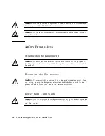
2. Peel the liner from the copper foil at the opposite end of the wrist strap and attach

the end to the metal part of the system.

See

FIGURE 7-8

.

FIGURE 7-8

Attaching the Wrist Strap to the System

Opening the Front of the System

Follow the procedure in Section “Opening the Rear of the System” on page 7-43
before you begin.

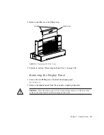
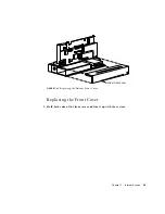
Removing the Filler Cover

This section applies to headless (no display panel) systems only. Otherwise, see
Section “Removing the Display Panel” on page 7-49.

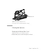
1. Loosen the two screws on the filler cover.

Wrist strap

Wrist strap

Summary of Contents for SPARCstation Voyager

Page 1: ...eedback sun com SPARCstation Voyager Service Manual Part No 801 3872 12 Revision A December 1994 Sun Microsystems Computer Company A Sun Microsystems Inc Business 901 San Antonio Road Palo Alto CA 943...

Page 2: ...FOR A PARTICULAR PURPOSE OR NON INFRINGEMENT Copyright 1997 Sun Microsystems Inc 901 San Antonio Road Palo Alto Californie 94303 4900 U S A Tous droits r serv s Ce produit ou document est prot g par u...

Page 3: ...Mode 7 Diagnostic Tools 9 OpenBoot PROM Diagnostics 10 SunDiag System Exerciser 12 3 Power On Self Test POST 15 Normal Mode 15 Diagnostic Mode 15 Setting Up a tip Connection to Another Workstation 16...

Page 4: ...28 Lines or Blank Areas on the Display Panel 28 Disk Drive or SCSI Errors 29 Testing the System SCSI Controller 29 Memory Errors 31 5 Safety and Tools Requirements 33 Safety Requirements 33 Symbols 33...

Page 5: ...emoving the Display Panel 49 Removing the Front Cover 50 Removing the Bottom Front Cover 51 Removing the Bottom Rear Cover 52 Closing the System 55 Replacing the Bottom Rear Cover 55 Replacing the Bot...

Page 6: ...g the DC DC Converter 72 SCSI Cable 72 Removing the SCSI Cable 72 Replacing the SCSI Cable 73 Floppy Cable 73 Removing the Floppy Cable 73 Replacing the Floppy Cable 76 Flex Cable 81 Removing the Flex...

Page 7: ...OD NVRAM 101 Video Board 101 Removing the Video Board 101 Replacing the Video Board 103 Memory Card 103 Removing the Memory Card 103 Replacing the Memory Card 104 IR Board 105 Removing the IR Board 10...

Page 8: ...126 Mono Display Panel Connector 128 Color Display Panel Connector 130 PCMCIA Connector s 131 Keyboard Mouse and Serial Port 133 Keyboard Mouse 133 ISDN Ports 134 ISDN TE 134 ISDN NT 134 Serial Port...

Page 9: ...Contents ix test memory 146 power off 147 Glossary 149...

Page 10: ...x SPARCstation Voyager Service Manual December 1994...

Page 11: ...t 1 Keyboard LEDs 21 FIGURE 3 4 Upper and Lower Memory Cards Location 22 FIGURE 3 5 Tests to Run After Running POST 23 FIGURE 4 1 Upper and Lower Memory Card Location 31 FIGURE 6 1 Power Key Location...

Page 12: ...Flex Connectors Location on the Video Board 53 FIGURE 7 15 Screw on the Floppy Drive Locking lever 54 FIGURE 7 16 Removing the Floppy Drive 54 FIGURE 7 17 Removing the Bottom Rear Cover 55 FIGURE 7 18...

Page 13: ...onnecting the DC DC Converter 78 FIGURE 8 14 Unlocking the Floppy Connector 79 FIGURE 8 15 Connecting the Floppy Cable to the Floppy Drive 79 FIGURE 8 16 Replacing the Video Board 80 FIGURE 8 17 Repla...

Page 14: ...emoving Positioning the CPU Board 98 FIGURE 10 6 Location of the TOD NVRAM 99 FIGURE 10 7 Removing Replacing the Speaker 102 FIGURE 10 8 Flex Connectors Location on the Video Board 102 FIGURE 10 9 Rem...

Page 15: ...IA Connector s 131 FIGURE B 9 Keyboard Mouse Connector 133 FIGURE B 10 ISDN TE Connector 134 FIGURE B 11 ISDN NT Connector 135 FIGURE B 12 Serial Port Connector 135 FIGURE B 13 Twisted Pair Ethernet C...

Page 16: ...xvi SPARCstation Voyager Service Manual December 1994...
Page 17: ...l Memory Address and Memory Locations 31 TABLE 11 1 Replacement Parts List 111 TABLE A 1 Color System Physical Specifications 117 TABLE A 2 Monochrome System Physical Specifications 117 TABLE A 3 Head...

Page 18: ...onnector Pin Assignments 134 TABLE B 11 ISDN TE Connector Pin Assignments 135 TABLE B 12 Serial Port Connector Pin Assignments 135 TABLE B 13 Twisted Pair Ethernet Pin Assignments 136 TABLE B 14 Flopp...

Page 19: ...The following table describes the typographic changes used in this book TABLE P 1 Typographic Conventions Typeface or Symbol Meaning Example AaBbCc123 The names of commands files and directories on s...

Page 20: ...re referenced in this manual TABLE P 2 Shell Prompts Shell Prompt C shell prompt machine_name C shell superuser prompt machine_name Bourne shell and Korn shell prompt Bourne shell and Korn shell super...

Page 21: ...he equipment Individuals who remove any outer panels or open covers to access this equipment must observe all safety precautions and ensure compliance with skill level requirements certification and a...

Page 22: ...xxii SPARCstation Voyager Service Manual December 1994...
Page 23: ...ard Mouse PCMCIA cards optional Memory cards optional Battery optional The following figures illustrate the SPARCstation Voyager workstation FIGURE 1 1 shows the front view of the unit FIGURE 1 2 show...

Page 24: ...ARCstation Voyager Service Manual December 1994 Systems Illustrations FIGURE 1 1 Front View Exploded Display panel Front cover Left cap Power supply Bottom front cover Power LED Power supply door IR l...

Page 25: ...Chapter 1 Product Description 3 FIGURE 1 2 Rear View Exploded Display panel Right cap Bottom rear cover Rear cover Back panel...

Page 26: ...al FIGURE 1 5 Back Panel Speaker SCSI cable Flex cable Video board Floppy drive Disk drive IR board TOD NVRAM DC DC converter Memory cards option CPU board I O board PCMCIA slots A TE NT ISDN Keyboard...

Page 27: ...types of AMLCD Active Matrix Liquid Crystal Display panels or video monitors Video monitors up to 1152 x 900 resolution are supported TABLE 1 1 lists the display panels supported TABLE 1 1 Display Pa...

Page 28: ...6 SPARCstation Voyager Service Manual December 1994...
Page 29: ...t Mode To troubleshoot a problem it is helpful to know what part of the system has control of system operations at any moment When you turn on the power control of the system passes in this order Open...

Page 30: ...apter 3 Power On Self Test POST If the POST passes the system probes for SBus devices and interprets their drivers Next high level tests are performed You will see the words Testing Memory while the h...

Page 31: ...s net See TABLE 2 1 To run user specified programs you must be at the ok prompt TABLE 2 1 describes the auto boot and diag switch parameters Diagnostic Tools The main categories of diagnostic tests ar...

Page 32: ...c Description Power On Self Test POST tells you if the CPU board or memory card fails POST code residing in the OpenBoot PROM executes at power on when you press and hold the Stop D keys or the diag s...

Page 33: ...l fail the external loopback phase If the tpe link test parameter is false disabled the external loopback test will appear to pass even if a cable is not connected test disk test disk0 test disk1 test...

Page 34: ...itch parameter to true watch clock Displays seconds from the system s Time of Day chip None watch net Monitors broadcast Ethernet packets on the Ethernet cable connected to the system A cable must be...

Page 35: ...tory opt SUNWdiag bin If the SunDiag system exerciser is not on the system hard disk or server you can load it from CD ROM For more information see the SunDiag User s Guide If the SunDiag tests pass t...

Page 36: ...14 SPARCstation Voyager Service Manual December 1994...
Page 37: ...he OpenBoot PROM Depending on the options set in the OpenBoot PROM for example if diag switch is disabled set to false and auto boot is enabled set to true the operating system will load Low level dia...

Page 38: ...t lets you use SunOS windowing and operating system features to help you work with the boot PROM 1 Connect the SPARCstation Voyager workstation serial port TTYa to another Sun workstation TTYa serial...

Page 39: ...ws the steps to POST and the options available FIGURE 3 1 How to Invoke POST Tests POST Runs Following is a sample listing from OpenBoot PROM version 2 15 or later versions of the diagnostic mode test...

Page 40: ...ern Test MMU TLB LCAM NTA Pattern Test IOMMU SBUS Config Regs Test IOMMU Control Reg Test IOMMU Base Address Reg Test IOMMU TLB Flush Entry Test IOMMU TLB Flush All Test SBus Read Timeout Test EBus Re...

Page 41: ...egister Test DMA P_BCNT Register Test PPORT Registers Test NVRAM Access Test TOD Registers test PMC Registers test PMC SCSI Power test PMC Audio Power Test PMC D A to A D Loop Test MIC Registers Test...

Page 42: ...en POST fails If a failure occurs in POST the keyboard displays a specific LED pattern See FIGURE 3 3 and TABLE 3 1 After POST is completed and during normal system operation the LEDs should not be in...

Page 43: ...aps Lock key fails to flash on and off after you have pressed and held the Stop D keys when you power on the system POST failed POST Error Messages The following are the possible POST error messages t...

Page 44: ...s the one located closest to the CPU board FIGURE 3 4 Upper and Lower Memory Cards Location After POST Ends Use FIGURE 3 5 to determine what diagnostics tests to run after the POST ends STATUS Power O...

Page 45: ...Chapter 3 Power On Self Test POST 23 FIGURE 3 5 Tests to Run After Running POST POST passed Use error messages displayed on TTY tip window or display panel Run on board diagnostics or SunDiag No Yes...

Page 46: ...24 SPARCstation Voyager Service Manual December 1994...
Page 47: ...ms Corrective Actions References Panel display is off Press the Shift Control or Alt key Press Power key Make sure all cable connections are secure See SPARCstation Voyager hardware setup or SPARCstat...

Page 48: ...keyboard power on key press the power switch at the rear of the system If power on succeeds the cable for the keyboard may be damaged or incorrectly connected Or the keyboard may be defective 6 The C...

Page 49: ...IA cards and try to run POST again If a test fails POST uses other keyboard LEDs to indicate which part of the system has failed See Section Power On Self Test on page 3 21 3 Observe the POST progress...

Page 50: ...ailable connect it to the 13W3 video port at the rear of the system and power on the system If data appears on the monitor the video board is not defective Replace the display panel 3 If no monitor is...

Page 51: ...scsi command TABLE 4 3 Troubleshooting Disk Drive Errors Symptom Corrective Action Read write or parity error reported by the operating system or applications Replace the disk drive indicated by the...

Page 52: ...SCSI address 7 to any device This address is reserved for the system SCSI controller 3 If external SCSI devices are connected to the system verify that all SCSI cables and the SCSI terminator are con...

Page 53: ...ocations FIGURE 4 1 Upper and Lower Memory Card Location TABLE 4 4 Physical Memory Address and Memory Locations Physical Memory Address Range Memory Location Bank 0 0000000 0ffffff 1000000 1ffffff CPU...

Page 54: ...ion TABLE 4 3 shows that this address is within the CPU on board memory range The CPU board should be replaced to correct this failure If memory errors occur between the address ranges of 2000000 and...

Page 55: ...all cautions warnings and instructions marked on the equipment Ensure that the voltage and frequency rating of the power outlet you use matches the electrical rating label on the equipment Never push...

Page 56: ...modifications to the equipment Sun Microsystems Inc is not responsible for regulatory compliance of a modified Sun product Placement of a Sun product Caution To ensure reliable operation of your Sun p...

Page 57: ...the real time clock SGS No MK48T08 Batteries are not customer replaceable parts They may explode if mistreated Do not dispose of the battery in fire Do not disassemble it or attempt to recharge it Re...

Page 58: ...a soft cloth dampened with water Tools Required Screwdriver Phillips 1 Hex nut driver 3 16 inches Flat blade screwdriver Grounding wrist strap Volt Ohmmeter VOM for checking voltages and continuity An...

Page 59: ...rt You must power off the system 1 Become superuser by typing su 2 Type your superuser password 3 Type init 0 4 Turn off the power to all external units External units can include external drives prin...

Page 60: ...from the keyboard port labeled on the back panel of the system Go to Step 1 7 Press the power switch on the back panel FIGURE 6 2 Power Switch Location 8 Disconnect the power source a For the system t...

Page 61: ...Chapter 6 Power Off and On 39 FIGURE 6 3 System With the Power Supply b For the system that runs on the battery There is no power cable to be disconnected Power supply AC power cable Wall outlet...

Page 62: ...em With the Battery Installed c For the system that contains a battery and runs on the power supply slow charging the battery Disconnect the external DC cable from the DC input connector on the back p...

Page 63: ...o the keyboard port labeled on the back panel of the system if your system has a keyboard 2 Connect the power source a For the system that runs on the power supply Connect the AC power cable to the po...

Page 64: ...5 3 Connect the cables to all external units See the manual supplied with each device for instructions 4 Turn on the power to all external units starting with the unit farthest electrically from the...

Page 65: ...m on page 6 37 before you begin Opening the Rear of the System Removing the Power Supply 1 Slide the power supply door to the unlock position and remove it FIGURE 7 1 Removing the Power Supply Door 2...

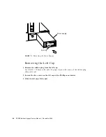
Page 66: ...Removing the Left Cap 1 Remove the rubber plug from the left cap See FIGURE 7 3 Puncture the end of a paper clip into the center of the rubber plug then pull it out 2 Loosen the two screws on the left...

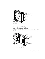
Page 67: ...ht Cap 1 Remove both rubber plugs from the right cap See FIGURE 7 4 If the lock block was installed you need to remove the top rubber plug only FIGURE 7 4 Removing the Right Cap Left cap Rubber plug S...

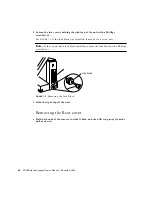
Page 68: ...If the lock block was installed loosen the top screw only Note If the system has a lock block installed remove the lock block with a Phillips screwdriver FIGURE 7 5 Removing the Lock Block 3 Slide the...

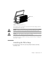
Page 69: ...cessor may be hot Avoid contact with these surfaces while they are hot Caution You must attach your wrist strap now Ordinary amounts of static from your clothes or work environment can destroy compone...

Page 70: ...f the system See FIGURE 7 8 FIGURE 7 8 Attaching the Wrist Strap to the System Opening the Front of the System Follow the procedure in Section Opening the Rear of the System on page 7 43 before you be...

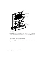
Page 71: ...Front Cover on page 7 50 Removing the Display Panel 1 Loosen the two Phillips screws behind the display panel See FIGURE 7 10 2 Remove the display panel from the system by wiggling it upward Caution P...

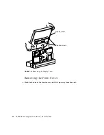
Page 72: ...Cstation Voyager Service Manual December 1994 FIGURE 7 10 Removing the Display Panel Removing the Front Cover Hold both ends of the front cover and lift it up away from the unit Display panel Captive...

Page 73: ...nal Access 51 FIGURE 7 11 Removing the Front Cover Now you have access to the video board speaker and floppy drive Removing the Bottom Front Cover Remove the bottom front cover by sliding it off the u...

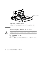
Page 74: ...ive the SCSI cable and the IR board Removing the Bottom Rear Cover Caution You must remove the display panel before laying the unit on its front to avoid possible damage to the panel 1 Lay the system...

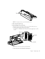
Page 75: ...The floppy drive must be moved to allow removal of the bottom rear cover a Disconnect the flex cable from the video board See FIGURE 7 14 Hold both ends of the connectors and wiggle them out of the so...

Page 76: ...Gently pull the locking lever toward the drive slide the floppy drive to the right and leave it hanging FIGURE 7 16 Removing the Floppy Drive 5 Hold and raise the bottom rear cover slightly then pull...

Page 77: ...tom Rear Cover Now you have access to the IR cable and the I O board Closing the System Replacing the Bottom Rear Cover Replace the bottom rear cover if it has been removed 1 Hold the bottom rear cove...

Page 78: ...r Cover 2 Replace the floppy drive a Position the floppy drive so that the four mounting feet are aligned with the four slots on the system See FIGURE 7 19 b Push the four mounting feet in the slots a...

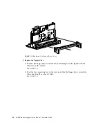
Page 79: ...e c Tighten the screw on the floppy drive locking lever FIGURE 7 20 Screw on the Floppy Drive Locking Lever d Connect the flex cable to the video board See FIGURE 7 20 Floppy drive Video board Slots f...

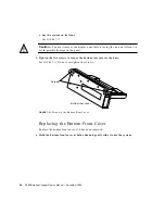
Page 80: ...void possible damage to the panel 3 Tighten the two screws to secure the bottom rear cover to the base See FIGURE 7 13 Do not overtighten the screws FIGURE 7 21 Screws in the Bottom Rear Cover Replaci...

Page 81: ...Chapter 7 Internal Access 59 FIGURE 7 22 Replacing the Bottom Front Cover Replacing the Front Cover 1 Hold both ends of the front cover and line it up with the system Bottom front cover...

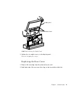
Page 82: ...gh the cutout at the center and the flange of the bottom front cover slides into the groove at the bottom of the front cover Replacing the Display Panel 1 Hold the display panel with both hands positi...

Page 83: ...2 Tighten the two captive screws on the display panel Do not overtighten the screws Replacing the Rear Cover 1 Remove the wrist strap from the system and your wrist 2 Hold both ends of the rear cover...

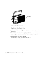
Page 84: ...r covers together and slide the right cap onto the unit See FIGURE 7 26 2 Tighten the two screws to secure the right cap on the unit Do not overtighten the screws If a lock block was installed tighten...

Page 85: ...ck installed insert the lock bock into the lower right cap hole and tighten the screw FIGURE 7 27 Replacing the Lock Block Replacing the Left Cap 1 Hold the front and rear covers together and slide th...

Page 86: ...wo screws to secure the left cap on the unit Do not overtighten the screws 3 Insert the rubber plug in the left cap FIGURE 7 28 Replacing the Left Cap Replacing the Power Supply 1 Insert the power sup...

Page 87: ...Chapter 7 Internal Access 65 FIGURE 7 29 Replacing the Power Supply 2 Replace the power supply door by sliding it to the locked position FIGURE 7 30 Replacing the Power Supply Door Power supply Door...

Page 88: ...66 SPARCstation Voyager Service Manual December 1994...
Page 89: ...69 DC DC Converter on page 70 SCSI Cable on page 72 Floppy Cable on page 73 Flex Cable on page 81 Refer to the following before you remove any part Safety Requirements on page 33 Powering Off the Sys...

Page 90: ...he Display Panel 1 Install the new display panel See Section Replacing the Display Panel on page 7 60 2 Replace the rear cover See Section Replacing the Rear Cover on page 7 61 3 Replace the right cap...

Page 91: ...acing the Power Supply 1 Replace the power supply See Section Replacing the Power Supply on page 7 64 2 Power on the system Section Powering On the System on page 6 41 Speaker Removing the Speaker 1 R...

Page 92: ...t the replacement speaker into its cavity See FIGURE 8 1 Make sure that the speaker cable is routed to the rear side of the system 2 Replace the CPU board on the system See Section Replacing the CPU B...

Page 93: ...verter Connector 2 Loosen the four threaded standoffs Use a 3 16 hex nut driver See FIGURE 8 3 3 Remove the DC DC converter FIGURE 8 3 Removing Replacing the DC DC Converter CPU board DC DC converter...

Page 94: ...ndoffs on the studs See FIGURE 8 3 3 Connect the DC DC converter connector to the CPU board connector See FIGURE 8 1 4 Close the system and power it on SCSI Cable Removing the SCSI Cable 1 Remove the...

Page 95: ...board socket 2 Replace the disk drive See Section Replacing the Hard Disk Drive on page 9 94 3 Close the system and power it on Floppy Cable Removing the Floppy Cable 1 Remove the CPU board See Secti...

Page 96: ...h ends of the connectors and wiggle them out of the sockets FIGURE 8 6 Flex Connectors Location on the Video Board d Remove all three screws from the video board See FIGURE 8 7 e Gently pull down the...

Page 97: ...t blade screwdriver or similar tool to push both ends of the connector locking device away from the drive Gently pull the floppy cable from the drive FIGURE 8 8 Removing the Floppy Cable From the Flop...

Page 98: ...e seated in the I O board socket FIGURE 8 9 Positioning the CPU Board b Connect the floppy cable to the CPU board See FIGURE 8 10 i Make sure the connector locking device is unlocked Use the tip of a...

Page 99: ...Connecting Disconnecting the Speaker Cable f Push the CPU board down so the card edge is seated in the I O board socket See FIGURE 8 12 Insert a screwdriver or similar tool through the openings at the...

Page 100: ...cing the CPU Board h Connect the DC DC converter connector to the CPU board FIGURE 8 13 Connecting the DC DC Converter i Tuck the pull tab behind the memory card 3 Connect the floppy cable to the flop...

Page 101: ...he drive FIGURE 8 14 Unlocking the Floppy Connector b Insert the floppy cable into the connector See FIGURE 8 15 c Push down both sides of the connector locking device to secure the floppy cable in th...

Page 102: ...e slot on the system b Insert and tighten the three mounting screws c Connect the flex cable to the video board See FIGURE 8 7 FIGURE 8 16 Replacing the Video Board 5 Replace the speaker Gently press...

Page 103: ...on Removing the Hard Disk Drive on page 9 92 2 Disconnect the flex cable from the video board FIGURE 8 18 Removing Replacing the Flex Cable from the Video Board 3 Snap open the bail locks at both ends...

Page 104: ...ng the Flex Cable 1 Connect the replacement flex cable to the CPU board See FIGURE 8 19 2 Snap in both bail locks to secure the flex connector to the CPU board 3 Connect the flex cable to the video bo...

Page 105: ...ve the hard disk drive See Section Removing the Hard Disk Drive on page 9 92 2 Disconnect the SCSI cable from the I O board FIGURE 8 20 Connecting Disconnecting the SCSI Cable the I O board 3 Disconne...

Page 106: ...Connection to the IR Board 4 Remove the two screws from the IR board Use a Phillips screwdriver FIGURE 8 22 Removing Replacing the IR Board 5 Remove the IR board Place it on an antistatic surface 6 Di...

Page 107: ...e FIGURE 8 23 2 Replace the IR board in the system and connect the IR cable to the IR board See FIGURE 8 21 3 Insert and tighten the two Phillips screws on the IR board See FIGURE 8 22 4 Connect the S...

Page 108: ...86 SPARCstation Voyager Service Manual December 1994...
Page 109: ...ear of the System on page 43 Attaching the Wrist Strap on page 47 Opening the Front of the System on page 48 Removing the Bottom Front Cover on page 51 Refer to the following after replacing any part...

Page 110: ...IGURE 9 2 Use the tip of a flat blade screwdriver or similar tool to release the connector locking device Pull the floppy cable out of the connector FIGURE 9 2 Removing the Floppy Cable From the Flopp...

Page 111: ...Screw on the Locking Lever 5 Gently pull the locking lever toward the drive slide the floppy drive to the right and pull it away from the unit FIGURE 9 4 Removing the Floppy Drive Floppy drive Lockin...

Page 112: ...to push both ends of the locking device away from the connector FIGURE 9 5 Unlocking the Floppy Connector 2 Insert the floppy cable into the floppy drive connector See FIGURE 9 6 FIGURE 9 6 Connectin...

Page 113: ...ts on the system FIGURE 9 7 Replacing the Floppy Drive 5 Push the four mounting feet in the slots and slide the floppy drive toward the video board until you hear the floppy locking lever click See FI...

Page 114: ...he flex cable to the video board See FIGURE 9 8 8 Close the system and power it on Hard Disk Drive Removing the Hard Disk Drive 1 Place an antistatic surface on your work area 2 Disconnect the SCSI ca...

Page 115: ...n the drive mounting bracket See FIGURE 9 10 FIGURE 9 10 Location of Screws on the Disk Drive Mounting Bracket Caution Handle the drive by its ends only Do not press on the top of the drive 4 Slide th...

Page 116: ...not press on the top of the drive 1 Position the replacement drive so both screws line up with the mounting holes See FIGURE 9 11 2 Tighten both screws to secure the drive into the unit 3 Connect the...

Page 117: ...age 105 I O Board on page 108 Refer to the following before you remove any part Safety Requirements on page 33 Powering Off the System on page 37 Opening the Rear of the System on page 43 Attaching th...

Page 118: ...stem unit Insert a screwdriver or similar tool through the openings at the top of the CPU board and the top of the chassis Use the tool as a lever to push the CPU board up Do not remove the CPU board...

Page 119: ...il lock ends from the flex connector and disconnect the connector from the CPU board See FIGURE 10 3 FIGURE 10 3 Disconnecting the Flex Cable from the CPU Board 7 Disconnect the speaker cable from the...

Page 120: ...the CPU board from the system FIGURE 10 5 Removing Positioning the CPU Board 9 Place the CPU board on an antistatic surface Replacing the TOD NVRAM Remove the TOD from your defective CPU board and in...

Page 121: ...raight up Gently wiggle the chip carrier as necessary 5 Carefully align the pins and insert the TOD in the socket of the replacement CPU board The carrier is keyed so the TOD can be installed only one...

Page 122: ...rd and the chassis Use the tool as a lever to push the board down into the socket on the I O board 7 Tighten the two screws on the CPU board See FIGURE 10 1 If the CPU board is not installed correctly...

Page 123: ...he replacement TOD on the CPU board See FIGURE 10 6 2 Carefully align the pins and insert the TOD into the socket The carrier is keyed so the TOD can be installed only one way 3 Push the TOD into the...

Page 124: ...from the video board See FIGURE 10 8 FIGURE 10 8 Flex Connectors Location on the Video Board 4 Remove the three screws from the video board See FIGURE 10 9 Use a Phillips screwdriver 5 Pull the video...

Page 125: ...tor should stick out of the slot on the system unit 2 Insert and tighten the three screws 3 Connect the flex cable to the video board See FIGURE 10 8 4 Gently press the speaker tabs and insert the spe...

Page 126: ...remove the memory card FIGURE 10 10 Removing the Memory Card Replacing the Memory Card 1 Push the replacement memory card all the way into the slot See FIGURE 10 11 The Sun logo on the memory card sho...

Page 127: ...memory card The pull tab interferes with the rear cover installation if not tucked in 3 Close the system and power it on IR Board Removing the IR Board 1 Remove the hard disk drive See Section Removi...

Page 128: ...nnecting Disconnecting the SCSI Cable the I O board 3 Disconnect the IR cable from the IR board See FIGURE 10 13 FIGURE 10 13 IR Cable Connection to the IR Board 4 Remove the two screws from the IR bo...

Page 129: ...rd 1 Position the replacement IR board in the unit See FIGURE 10 14 2 Install both screws to secure the IR board to the unit 3 Connect the IR cable to the IR board See FIGURE 10 13 4 Connect the SCSI...

Page 130: ...2 Disconnect the SCSI cable from the I O board FIGURE 10 15 Connecting Disconnecting the SCSI Cable the I O board 3 Remove the CPU board Section Removing the CPU Board on page 10 96 4 Disconnect the...

Page 131: ...Remove the screw from the I O board See FIGURE 10 17 FIGURE 10 17 Screw Location at the Bottom of I O Board 8 Grasp the I O board at both ends and gently lift it up and out of the unit See FIGURE 10 1...

Page 132: ...nel See FIGURE 10 16 3 Tighten the screw on the I O board See FIGURE 10 17 4 Connect the DC power harness to the I O board See FIGURE 10 16 5 Connect the IR cable to the I O board See FIGURE 10 16 6 C...

Page 133: ...representative or service provider to confirm part numbers before you order new or replacement parts TABLE 11 1 Replacement Parts List Replacement Parts Part Number Description CPU Board 501 2581 Assy...

Page 134: ...320 1200 Sun Compact 1 Keyboard German 320 1206 Sun Compact 1 Keyboard Swedish 320 1210 Sun Compact 1 Keyboard UK 320 1213 Sun Compact 1 Keyboard UNIX Logoless 320 1214 Sun Compact 1 Keyboard Japan Lo...

Page 135: ...Cord Assy N American 530 2122 Power Cord Assy Japanese Door 540 2493 Battery Door 540 2494 Power Supply Door ACCESSORIES Battery Pack 595 3146 Battery Pack Microphone 370 1678 Microphone Screw Cover 3...

Page 136: ...Cstation Voyager Service Manual December 1994 Illustrated Parts Breakdown FIGURE 11 1 Front View Exploded Display panel Front cover Left cap Power supply Bottom front cover Power LED Power supply door...

Page 137: ...Chapter 11 Replacement Parts 115 FIGURE 11 2 Rear View Exploded Display panel Right cap Bottom rear cover Rear cover Back panel...

Page 138: ...nual December 1994 FIGURE 11 3 Front View Internal FIGURE 11 4 Rear View Internal Speaker SCSI cable Flex cable Video board Floppy drive Disk drive IR board TOD NVRAM DC DC converter Memory cards opti...

Page 139: ...cations U S Metric Height 13 5 in 34 4 cm Width 14 3 in 36 2 cm Depth 5 4 in 13 8 cm Weight system w power supply 13 2 lb 6 0 kg TABLE A 2 Monochrome System Physical Specifications U S Metric Height 1...

Page 140: ...2 cm Depth 5 4 in 13 8 cm Weight system w power supply 7 9 lb 3 6 kg TABLE A 4 AC DC Power Supply Specifications Parameter Value Input Voltage range 100 to 120 VAC or 200 to 240 VAC Current maximum 1A...

Page 141: ...Operating Non operating U S Metric U S Metric Temperature 32 to 104 F 0 to 40 C 13 140 F 25 to 60 C Humidity 5 to 93 RH 5 to 93 RH 5 to 93 RH 5 to 93 RH Altitude 10 2 psi 9843 ft 70kPa 3 0 km 3 6 psi...

Page 142: ...120 SPARCstation Voyager Service Manual December 1994...

Page 143: ...signments Pin Name I O Description Pin Name I O Description 1 batt_rtn O Battery Return 6 batt_ac I Battery AC 2 batt_rtn O Battery Return 7 batt_vsp1 I Battery Voltage Supply 3 batt_txd I Battery Tra...

Page 144: ...B 3 Battery Power Connector TABLE B 2 Battery Signal Connector Pin Assignments Pin Name I O Description Pin Name I O Description 1 batt_rxd O Battery Receive Data 4 batt_vsp1 I Battery Voltage Supply...

Page 145: ...MPWR O B7 SCSI_DATA 0 I O A8 SCS_BUSY I B8 SCSI_DATA 1 I O A9 SCSI_ACK I B9 SCSI_DATA 2 I O A10 SCSI_MESSAGE O B10 SCSI_DATA 3 I O A11 SCSI_SEL O B11 SCSI_DATA 4 I O A12 SCSI_CONTROL O B12 SCSI_DATA 5...

Page 146: ...A32 GND G gnd B32 GND G gnd A33 SHIELD B33 SHIELD A34 B34 A35 B35 A36 B36 A37 ISDN_TE_1 I O B37 ISDN_NT_1 I O A38 ISDN_TE_3 I O B38 ISDN_NT_3 I O A39 ISDN_TE_2 I O B39 ISDN_NT_2 I O A40 ISDN_TE_4 I O...

Page 147: ...A64 fd_motor_en O B64 SP_RTXC I A65 fd_desnsity_sel O B65 SP_RTS O A66 fd_dir O B66 SP_RXD I A67 fd_step O B67 SP_TRXC I A68 fd_wr_data O B68 SP_TXD O A69 fd_wr_en O B69 KBD_PWR O A70 fd_track0 I B70...

Page 148: ...12v A6 GND gnd B6 sb_ack 2 I O A7 sba 22 I O B7 sba 23 I O A8 sba 20 I O B8 sba 21 I O A9 sba 18 I O B9 sba 19 I O A10 sb_ack 1 I O B10 VCC vcc A11 sba 16 I O B11 sba 17 I O A12 sba 14 I O B12 sba 15...

Page 149: ...bd 15 I O A35 sbd 12 I O B35 sbd 13 I O A36 sbd 11 I O B36 GND gnd A37 sbd 9 I O B37 sbd 10 I O A38 sbd 7 I O B38 sbd 8 I O A39 VCC vcc B39 sbd 6 I O A40 sbd 4 I O B40 sbd 5 I O A41 sbd 2 I O B41 sbd...

Page 150: ...nd B55 VGND gnd A56 B56 VID_CLK O A57 VID_TXD O B57 VID_RXD I A58 batt_vspl O B58 batt_rtn I A59 batt_vspl O B59 batt_rtn I A60 batt_vspl O B60 batt_rtn I TABLE B 6 Mono Display Panel Pin Assignments...

Page 151: ...19 53 20 54 21 55 GND gnd 22 FLCD 0 O 56 FLCD 1 O 23 FLCD 2 O 57 FLCD 3 O 24 GND gnd 58 FLCD 4 O 25 FLCD 5 O 59 FLCD 6 O 26 FLCD 7 O 60 GND gnd 27 FLCD 8 O 61 FLCD 9 O 28 FLCD 10 O 62 FLCD 11 O 29 GND...

Page 152: ...me I O 1 GND gnd 35 TAB RX I 2 TAB TX O 36 PWR 5V pwr 3 37 4 BATT_RTN I 38 BRIGHT O 5 OHSYNC I 39 BATT_RTN I 6 BATT_RTN I 40 BATT_RTN I 7 BLENB I 41 BATT O 8 BATT O 42 BATT O 9 GND gnd 43 FPS2 I 10 FP...

Page 153: ...62 R10 O 29 GND gnd 63 R03 O 30 R02 O 64 R01 O 31 R00 O 65 GND gnd 32 FHS O 66 GND gnd 33 FVS O 67 GND gnd 34 FDCLK O 68 GND gnd TABLE B 8 PCMCIA Pin Assignments Pin Name I O Description Pin Name I O...

Page 154: ...1 17 Vcc 51 Vcc 18 Vpp1 Prgrm periph supply 52 Vpp2 Prgrm periph supply 2 19 A16 I Address bit 16 53 A22 I Address bit 22 20 A15 I Address bit 15 54 A23 I Address bit 23 21 A12 I Address bit 12 55 A24...

Page 155: ...it 10 33 IOIS16 O IO port is 16 bit 67 CD2 O Card detect 34 GND Ground 68 GND Ground TABLE B 9 Keyboard Mouse Connector Pin Assignments Pin Name I O Description Pin Name I O Description 1 GND Ground 5...

Page 156: ...1 FIGURE B 10 ISDN TE Connector ISDN NT This connector is located on the I O board and is designated J0302 TABLE B 10 ISDN TE Connector Pin Assignments Pin Name I O Pin Name I O 1 isdn_te_ps3_p I O 5...

Page 157: ...O 6 isdn_nt_4 I O 3 isdn_nt_1 I O 7 isdn_nt_ps2_n I O 4 isdn_nt_2 I O 8 isdn_nt_ps2_p I O TABLE B 12 Serial Port Connector Pin Assignments Pin Name I O Description Pin Name I O Description 1 14 2 sp_t...

Page 158: ...the system board and is designated as J1200 9 22 10 23 11 24 sp_txc O Transmit Clock 12 25 13 TABLE B 13 Twisted Pair Ethernet Pin Assignments Pin Name I O Description Pin Name I O Description 1 tpe_...

Page 159: ...D O Ground 3 VCC O Voltage 16 fd_wr data O Write Data 4 fd_drv sel O Drive Select 17 GND O Ground 5 VCC O Voltage 18 fd_wr en I Write Enable 6 fd_dsk chng I Disk Change 19 GND O Ground 7 20 fd_track 0...

Page 160: ...10 N C 35 scsi attention I O Attention 11 VCC O Voltage 36 scsi busy I O Busy 12 VCC O Voltage 37 GND O Ground 13 GND O Ground 38 scsi ack I O Acknowledge 14 GND O Ground 39 scsi reset I O Reset 15 GN...

Page 161: ...i data 4 I O Data bit 4 6 GND O Ground 31 scsi data 5 I O Data bit 5 7 GND O Ground 32 scsi data 6 I O Data bit 6 8 GND O Ground 33 scsi data 7 I O Data bit 7 9 GND O Ground 34 scsi parity I O Parity...

Page 162: ...e CPU board and is designated as J0700 22 GND O Ground 47 scsi sel I O Select 23 GND O Ground 48 scsi control I O Control 24 GND O Ground 49 scsi req I O Request 25 GND O Ground 50 scsi dir I O Direct...

Page 163: ...tput The Headphone Output connector is located on the CPU board and is designated as J0602 TABLE B 18 Audio Line Input Pin Assignments Pin Name I O Description 1 GND O Ground 2 line in 1 I Line in lef...

Page 164: ...nual December 1994 FIGURE B 20 Audio Connector Headphone Output TABLE B 20 Audio Headphone Output Pin Assignments Pin Name I O Description 1 GND O Ground 2 head out l O Headphone output left 3 head ou...

Page 165: ...operating system may cause damage to data files test Device Alias test Device Pathname on page 143 test all on page 144 watch clock on page 144 watch net watch tpe on page 145 probe scsi on page 146 t...

Page 166: ...reference The diag switch parameter must be set true to run this test watch clock Displays seconds from the NVRAM TOD Non Volatile RAM Time of Day The counter counts from 0 to 59 repeatedly For examp...

Page 167: ...net interface also called twisted pair Ethernet or TPE You can also use watch tpe to monitor the 10BaseT TPE connection For example ok watch net Internal loopback test succeeded External loopback test...

Page 168: ...f Mbytes being tested is displayed and counted down to zero during the test If the diag switch parameter is false this test uses the selftest megs parameter in NVRAM to determine how much memory to te...

Page 169: ...Appendix C Selected On Board Diagnostics 147 power off This commands turn the power off You must have a Compact 1 or type 5 keyboard attached in order to use this command...

Page 170: ...148 SPARCstation Voyager Service Manual December 1994...
Page 171: ...eset value that is assumed to be correct unless changed by the user Desktop Storage Module An external data storage that contains a disk drive or a tape drive Abbreviated as DSM Desktop Storage Pack A...

Page 172: ...n your SPARCstation Voyager workstation point to point protocol PPP The successor to SLIP PPP provides router to router and host to network connections over both synchronous and asynchronous circuits...

Page 173: ...rd 123 CPU to Video board 126 external battery 121 floppy 136 internal battery 122 ISDN NT 134 ISDN TE 134 keyboard mouse 133 mono display panel 128 PCMCIA 131 power 121 SCSI external 139 SCSI interna...

Page 174: ...ble 73 floppy drive 87 floppy drive locking lever screw 54 forth toolkit 10 front cover 51 front view exploded 114 external 2 internal 4 116 H hard disk drive 92 headless system 48 I I O Board 108 ill...

Page 175: ...pair ethernet 136 placement of a Sun product 34 POST 10 21 error messages 21 power key 38 LED 20 off 37 on 41 does not succeed 26 switch 38 power cord connection 34 power supply 69 door 65 specificat...

Page 176: ...loppy connector 136 internal battery connector 122 ISDN NT 134 ISDN TE 134 keyboard mouse 133 SCSI connector external 139 SCSI connector internal 137 serial port 133 135 twisted pair ethernet 136 sign...

Page 177: ...155 tools required 36 troubleshooting tips 25 twisted pair ethernet TPE 145 U user specified programs 9 V video board 101 103 voltage 27 W watch clock 12 144 watch net 12 145 watch tpe 12 145 wrist st...

Page 178: ...156 SPARCstation Voyager Service Manual December 1994...
Reviews: