Chapter 8
Major Subassemblies
77
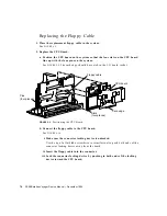
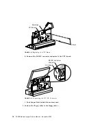
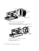
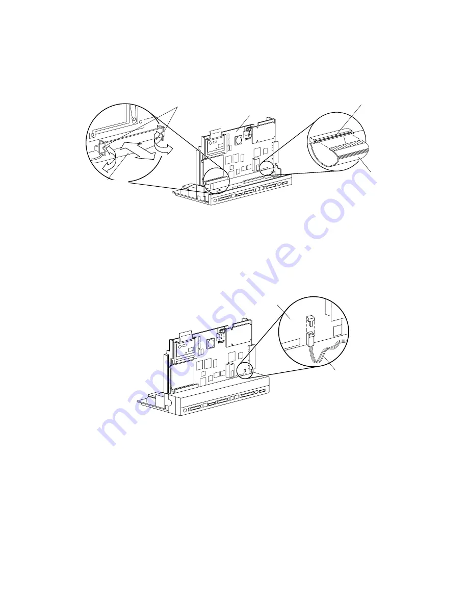
FIGURE 8-10
Connecting the Floppy and Flex Cables to the CPU Board
c. Connect the flex cable to the CPU board.
d. Snap in both bail locks to lock the flex connector on the CPU board.
e. Connect the speaker cable to the CPU board.
See
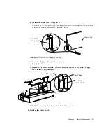
FIGURE 8-11
.
FIGURE 8-11
Connecting/Disconnecting the Speaker Cable
f. Push the CPU board down so the card edge is seated in the I/O board socket.
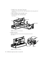
See
FIGURE 8-12
. Insert a screwdriver or similar tool through the openings at the
top of the CPU board and the chassis. Use the tool as a lever to push the CPU
board down into the socket on the I/O board.
g. Replace and tighten the two screws on the CPU board.
See
FIGURE 8-12
.
Floppy cable
CPU board
Flex cable
Bail locks
Connector
locking device
Speaker cable
CPU board
Summary of Contents for SPARCstation Voyager
Page 9: ...Contents ix test memory 146 power off 147 Glossary 149...
Page 10: ...x SPARCstation Voyager Service Manual December 1994...
Page 16: ...xvi SPARCstation Voyager Service Manual December 1994...
Page 22: ...xxii SPARCstation Voyager Service Manual December 1994...
Page 28: ...6 SPARCstation Voyager Service Manual December 1994...
Page 36: ...14 SPARCstation Voyager Service Manual December 1994...
Page 46: ...24 SPARCstation Voyager Service Manual December 1994...
Page 88: ...66 SPARCstation Voyager Service Manual December 1994...
Page 108: ...86 SPARCstation Voyager Service Manual December 1994...
Page 142: ...120 SPARCstation Voyager Service Manual December 1994...
Page 170: ...148 SPARCstation Voyager Service Manual December 1994...
Page 178: ...156 SPARCstation Voyager Service Manual December 1994...


