background image

7-1

C H A P T E R

7

Sun StorEdge 3120 SCSI Array FRUs

This chapter provides instructions for removing and installing field-replaceable units
(FRUs) which are specific to the Sun StorEdge 3120 SCSI array. FRU components can
be replaced by customers or by Sun service representatives.

At this time, there is only one FRU procedure which is unique to the Sun StorEdge
3120 SCSI array.

Note –

Be sure to follow

“Static Electricity Precautions” on page 1-5

for all

procedures.

7.1

Installing an Expansion Chassis FRU

The Sun StorEdge 3120 SCSI array box FRU includes a chassis, its drive midplane,
and its backplane. This product is ordered to replace a box that has been damaged or
whose midplane, backplane, or terminator module has been damaged.

To make a fully functional array, you need to add the following parts from the
replaced array:

Drive modules

Two power supply/fan modules

To install the individual modules, use the replacement instructions provided in this
guide.

To configure the array, refer to the installation manual for your array, located on
your Sun StorEdge 3000 Family Documentation CD.

To replace the chassis frame of an existing JBOD, perform the following steps.

Summary of Contents for StorEdge 3000 Series

Page 1: ...Sun Microsystems Inc www sun com Submit comments about this document at http www sun com hwdocs feedback Sun StorEdge 3000 Family FRU Installation Guide Part No 816 7326 17 May 2004 Revision A ...

Page 2: ... DISCLAIMERS ARE HELD TO BE LEGALLY INVALID Copyright 2003 22004 Dot Hill Systems Corporation 6305 El Camino Real Carlsbad Californie 92009 Etats Unis Tous droits réservés Sun Microsystems Inc et Dot Hill Systems Corporation peuvent avoir les droits de propriété intellectuels relatants à la technologie incorporée dans le produit qui est décrit dans ce document En particulier et sans la limitation ...

Page 3: ...Installing a New Disk Drive 2 5 2 1 4 Scanning the New Drive and Related Procedures 2 6 2 1 4 1 Scanning the New Drive 2 6 2 1 4 2 Checking and Performing the Correct Powerup Sequence 2 7 2 1 4 3 Assigning a Disk Drive as a Spare 2 8 2 1 4 4 If the Logical Drive Status is REBUILDING 2 9 2 1 4 5 Automatic Rebuild and Automatic Global Spare Assignments After a Failed Drive is Replaced 2 9 2 2 Instal...

Page 4: ... 3 2 1 1 Removing an AC Power Supply Fan Module 3 5 3 2 1 2 Installing an AC Power Supply Fan Module 3 6 3 2 2 Replacing a DC Power Supply Fan Module 3 6 3 2 2 1 Removing a DC Power Supply Fan Module 3 6 3 2 2 2 Installing an DC Power Supply Fan Module 3 7 4 Battery FRUs 4 1 4 1 Battery Operation 4 2 4 2 Battery Status on the Initial Firmware Screen 4 2 4 3 Battery Dating on the Battery Labels 4 3...

Page 5: ...cing I O Expansion Modules 5 11 5 2 1 Removing the I O Expansion Module 5 11 5 2 2 Installing the I O Expansion Module 5 11 5 3 Installing Small Form Factor Pluggable Transceivers 5 12 5 4 Installing a RAID Expansion Chassis FRU 5 14 5 5 Converting an FC JBOD into an FC RAID Array 5 17 6 SCSI Module FRUs 6 1 6 1 Replacing a SCSI Controller Module 6 2 6 1 1 Saving the Configuration Settings to NVRA...

Page 6: ...g the EMU Module 6 10 6 4 1 Removing an EMU Module 6 10 6 4 2 Installing an EMU Module 6 11 6 5 Installing a RAID Expansion Chassis FRU 6 11 6 6 Special JBOD Usage With External Terminators 6 14 6 6 1 External Terminators for Special Dual Bus JBOD Maintenance 6 15 6 6 2 Older JBOD Dual Bus Configurations 6 16 6 7 Installing a Filler Panel on a SCSI Array 6 19 7 Sun StorEdge 3120 SCSI Array FRUs 7 ...

Page 7: ...FC arrays are identical except where differences are identified in this manual Instructions are also included for FRUs which are common to all four arrays These FRU components can be replaced by customers or by Sun service representatives This chapter covers the following topics Available FRUs on page 1 2 Static Electricity Precautions on page 1 5 Powering Off the Array on page 1 5 Removal and ins...

Page 8: ... in the same chassis but not spindle speed RPMs on the same SCSI bus For instance you can use 36 Gbyte and 73 Gbyte drives with no performance problems if both are 10K RPM drives Violating this configuration guideline leads to poor performance TABLE 1 1 List of Available FRUs for the Sun StorEdge 3120 SCSI Array FRU Model Number Description F370 6195 xx 1U JBOD LVD Chassis I O board with SAF TE F3...

Page 9: ... F370 5403 xx Controller module 512 memory battery 2U LVD F370 5399 xx Terminator module F540 5522 xx Drive module 36GB LVD 10K RPM F540 5563 xx Drive module 73GB LVD 10K RPM F370 5398xxAC AC power and fan module 2U F370 5527 xxDC DC power and fan module 2U F370 5533 xx Battery LVD F370 5405 xx Cable LVD 1 foot jumper F370 5528 xx Cable LVD 1 5 foot expansion F370 5393 xx Box 2U JBOD LVD F370 5524...

Page 10: ...36GB FC 15KRPM XTA 3510 73GB 10K Drive module 73GB FC 10KRPM XTA 3510 146GB 10K Drive module 146GB FC 10KRPM XTA 3000 AMBS Air Management Sled XSFP SW 2GB SFP 2G SW 850NM FC TRANS XSFP LW 2GB SFP 2G LW 1310NM FC TRANS TABLE 1 4 List of Available FRUs for the Sun StorEdge 3511 FC Array FRU Model Number Description F370 6775 xx Box 2U FC Chassis Backplane RAID JBOD F370 5545 xx Battery FC 2U F370 55...

Page 11: ...es are either hot serviceable or hot swappable except for the chassis replacment procedure However you might need to power off the array both power supplies if you relocate the array or perform certain maintenance procedures with its associated servers Caution If controllers are not shut down from the firmware application or the CLI before an array is powered off data that is written to cache and ...

Page 12: ...1 6 Sun StorEdge 3000 Family FRU Installation Guide May 2004 3 Power off both power supply fan modules ...

Page 13: ...2 5 Scanning the New Drive and Related Procedures on page 2 6 Scanning the New Drive on page 2 6 Checking and Performing the Correct Powerup Sequence on page 2 7 Assigning a Disk Drive as a Spare on page 2 8 If the Logical Drive Status is REBUILDING on page 2 9 Automatic Rebuild and Automatic Global Spare Assignments After a Failed Drive is Replaced on page 2 9 Installing an Air Management Sled on...

Page 14: ...ront View of a Drive Module Pulled Out of the Chassis Caution When you replace a disk drive the disk drive must have the same capacity or greater of the disk drive which is being replaced You can mix capacity in the same chassis but not spindle speed RPMs on the same bus For instance you can use 36 Gbyte and 73 Gbyte drives with no performance problems if both are 10K RPM drives Violating this con...

Page 15: ...om the Main Menu choose view and edit scsi Drives b Locate the disk drive that has a status of BAD or FAILED in the Status column Write down the Channel number and SCSI target ID of the defective disk drive from the Chl and ID columns Write down the number of the associated logical drive as shown in the LG_DRV column that the defective disk drive is a member of 7 Physically locate the defective di...

Page 16: ... press Return e Type a time interval and press Return FIGURE 2 2 Identify Drive Option by all Flashing LEDs But the Selected Drive f Confirm your choice by selecting Yes and pressing Return The read write LED of all drives except the selected drive flash 2 1 2 Removing a Defective Disk Drive Caution Failure to identify the correct disk drive may result in replacing the wrong disk drive and could c...

Page 17: ...he plastic front bezel away from the front of the unit so that it drops down and is supported by the two hinged brackets on the sides 2 Turn the thumbscrew of the defective disk drive counterclockwise several full turns until the thumbscrew and drive module are loosened 3 Gently pull the release handle upward 4 Pull the drive module out until the drive connector has fully disconnected from the mid...

Page 18: ...to lock the locks 6 If the replaced drive is in a JBOD directly attached to a server perform any operations your host software requires to recognize the new drive and bring it under software control 7 Go to Scanning the New Drive and Related Procedures on page 2 6 2 1 4 Scanning the New Drive and Related Procedures 2 1 4 1 Scanning the New Drive After you have replaced a disk drive perform the fol...

Page 19: ...f it changes the logical drive status to GOOD 1 Power up the RAID array and associated server as follows Expansion unit s first RAID array next TABLE 2 1 Decision Table for Selecting Disk Drive Procedure If this drive status occurs Perform this task If the target logical drive status is GOOD the spare disk has successfully protected it and is now integrated into the logical drive and the replaceme...

Page 20: ...data a On the firmware Main Menu choose view and edit Configuration parameters and press Return b Choose Drive side SCSI Parameters and press Return c Choose Disk Access Delay Time and press Return d Change the value to 60 seconds and press Return e Select Yes to confirm the setting f Reboot the system g Check the logical drive status in the view and edit Logical drive window If the status is GOOD...

Page 21: ...tive drive and make the new drive a global spare while the rebuilding process continues This procedure installs the new drive and assigns it as a global spare so that automatic rebuild of a logical drive will occur if a drive fails on any other logical drive Note If a disk drive fails on another logical drive prior to the assignment of a new global spare you will have to manually rebuild the logic...

Page 22: ...e removal that occurs after the controller has been powered on The controller detects drive removal only when a host attempts to access the data on the drive 1 Choose view and edit Configuration parameters Drive side SCSI Parameters Periodic Auto Detect Failure Drive Swap Check Time A list of intervals is displayed 2 Choose an interval A confirmation message is displayed 3 Choose Yes to confirm th...

Page 23: ...to maintain the optimum airflow inside the chassis You can install the air management sled by using the same procedure as Installing a New Disk Drive on page 2 5 2 3 Adding or Removing the Tabletop Cover You can make a rack ready array into a tabletop array or make a tabletop array into a rack ready array These procedures require attaching or removing a tabletop cover also known as a tabletop skin...

Page 24: ...ews which attach the front ears to the rack and which attach the array to the back brackets of the rack b Slide the array out of the rack c Remove the screws which attach the side rails to the array and store the rails and related screws 4 On the top of the array remove the top two back center screws with a Phillips No 1 screwdriver and discard these screws 5 Slide the back of the array into the f...

Page 25: ...RE 2 4 Sliding the Chassis Into the Tabletop Cover FIGURE 2 5 Attaching the Chassis Ears to the Tabletop Cover 9 Put the caps back onto the ears Back of RAID product Front of tabletop cover Front of RAID product Screws to attach the cover to the chassis ears Chassis ear LEDs ...

Page 26: ...also Note the location of the chassis bezel holes on each ear 2 Remove the caps from the front left and right ears of the array by squeezing and pressing each cap towards the center of the chassis until it is free 3 Remove the 10 32 x 1 4 inch Phillips panhead screws which attach the tabletop cover to the array with a Phillips No 2 screwdriver and discard these screws 4 On the top of the array rem...

Page 27: ...e 3 2 Replacing Power Supply Fan Modules for 1U Arrays on page 3 5 The following power specifications apply to the power supply and fan modules TABLE 3 1 Power Specifications AC power Voltage and frequency 90 to 264 VAC 47 to 63 Hz Input current 5A max Power supply output voltages 5 VDC and 12 VDC DC power 48V DC 36 VDC to 72 VDC ...

Page 28: ...ons on page 1 5 1 Turn off the power and then remove the AC cord locks if applicable and the power cable 2 Turn the thumbscrew at the top of the power supply latch counterclockwise until the thumbscrew is disengaged from the power supply FIGURE 3 1 The Power Supply Partially Pulled out of the Chassis 3 Pull the latch forward about 45 degrees to disconnect the power supply fan module from the midpl...

Page 29: ...e to equipment do not remove a power supply fan module without a working replacement 3 1 3 1 Removing a DC Power Supply Fan Module Be sure to follow Static Electricity Precautions on page 1 5 1 Use a flatblade screwdriver to loosen the two screws that secure the power cable to the power supply and then disconnect the cable from the supply 2 Turn the thumbscrew at the top of the power supply latch ...

Page 30: ...DC power cables provided with the array Check the DC cable part number and wire labels carefully before connecting the cable to the source see the table below GND Chassis Ground 5 To extend the length of the DC power cable as needed Strip the last 1 4 inch of the cable insert it into a provided Panduit tube and crimp the tube 6 Attach the power cable to the RAID product 7 Turn the power on TABLE 3...

Page 31: ...ity Precautions on page 1 5 2 Turn off the power and then remove the AC cord locks if applicable and the power cable 3 Turn the thumbscrew at the top of the power supply latch counterclockwise until the thumbscrew is disengaged from the power supply FIGURE 3 2 The Power Supply Partially Pulled out of the Chassis 4 Pull the latch forward about 90 degrees to disconnect the power supply fan module fr...

Page 32: ...lockwise a quarter turn 4 Attach the power cable and reinstall the AC cord locks if applicable 5 Turn the power back on 3 2 2 Replacing a DC Power Supply Fan Module Caution To avoid damage to equipment do not remove a power supply fan module without a working replacement 3 2 2 1 Removing a DC Power Supply Fan Module 1 Be sure to follow Static Electricity Precautions on page 1 5 2 Turn off the powe...

Page 33: ...finger tight tighten it with a screwdriver and then loosen the thumbscrew counterclockwise a quarter turn 4 Connect the DC power cable to the DC source Note Use only DC power cables provided with the array Check the DC cable part number and wire labels carefully before connecting the cable to the source see the table below GND Chassis Ground 5 To extend the length of the DC power cable as needed S...

Page 34: ...3 8 Sun StorEdge 3000 Family FRU Installation Guide May 2004 ...

Page 35: ...tery on each controller module The battery dating information is the same for all batteries Topics covered in this chapter are Battery Operation on page 4 2 Battery Status on the Initial Firmware Screen on page 4 2 Battery Dating on the Battery Labels on page 4 3 Replacing a Battery on page 4 5 Replacing a SCSI Battery on page 4 5 Replacing an FC Battery on page 4 8 FC Battery Status and In Servic...

Page 36: ...ture returns to the normal range battery charging resumes and the battery status is reported correctly It is not necessary to replace or otherwise interfere with the battery in this situation The battery LED on the far right side of the controller module is an amber LED if the battery is bad or missing The LED blinks green if the battery is charging and is solid green when the battery is fully cha...

Page 37: ...battery does not have a serial number part number label the manufacture date for the battery is August 2002 TABLE 4 1 Battery Status Indicators Battery Display Description Discharged the battery is automatically recharged when it reaches this state Adequately charged to maintain cache memory for 72 hours or more in case of power loss Automatic recharging occurs when the battery status drops below ...

Page 38: ...abel Example for the Sun StorEdge 3510 FC Array In FIGURE 4 1 the number below the bottom bar code is the part number for example 3705555 04 0000044 02403000001 3705555 04 Date code of manufacture yyww year week Battery Serial number Part number Date code of manufacture yyww year week Battery Part number Serial number 0000043 0303000274 66 00000057 50 ...

Page 39: ...attery date 3 To replace the battery pull out the controller module completely 4 Disconnect the battery connector from the controller module 5 With a screwdriver remove the battery screws to release the battery from the battery module 6 Lift out the battery 7 Insert the new battery and attach the battery connector to the controller module 8 With a screwdriver attach the battery to the controller w...

Page 40: ...4 6 Sun StorEdge 3000 Family FRU Installation Guide May 2004 FIGURE 4 3 The Battery and Connector in a SCSI Array FIGURE 4 4 The Battery Connector Unplugged in a SCSI Array Battery Connector ...

Page 41: ...ter 4 Battery FRUs 4 7 FIGURE 4 5 The Underside of the Battery Module With Screws Being Removed FIGURE 4 6 The Top Side of the Controller Module With the Battery Being Lifted Out and the Connector Unplugged ...

Page 42: ...y battery perform the following steps 1 Turn the thumbscrews on the left and right sides of a battery module for the FC array counterclockwise until the thumbscrews are disengaged from the chassis 2 Hold the thumbscrews and pull out the battery module to check the battery date 3 To replace the battery pull out the battery module completely and disconnect the battery connector from the battery modu...

Page 43: ...URE 4 5 5 Lift out the battery 6 Insert the new battery and attach the battery connector to the battery module 7 With a screwdriver attach the battery to the controller with the screws that you removed in Step 4 8 Reinsert the battery module into the array and tighten the module thumbscrews firmly to secure the module 9 Set the in service dates for the new FC battery replacement with the CLI or SS...

Page 44: ...e must be set manually with the show battery status command after the battery FRU module is installed The show battery status command will prompt you to set the in service date to the system clock date Run this command immediately to ensure the battery status is accurate when you run the show battery status command in the future For redundant controllers status for both batteries is shown Status v...

Page 45: ...fying the In Service Date When Replacing a Battery in SSCS on page 4 13 The enclosure icon on the main window displays a degraded yellow status 21 days before the battery is going to expire The enclosure icon also displays a warning yellow status if the in service date has not been set for a battery FRU A critical red status is displayed when a battery has expired sccli show battery status Upper B...

Page 46: ... View View Enclosure or double click the enclosure The View Enclosure window is displayed showing the battery status in the Summary box To view battery information including type status manufacture date in service date and expiration date click Battery The Battery Information window is displayed ...

Page 47: ...ure icon displays a degraded yellow status symbol as shown in the following example 1 Double click the enclosure icon Sun StorEdge Configuration Service calculates the battery expiration date using the in service date date that the battery is put into service which is based on the host clock The program prompts you to verify the date by displaying the following message ...

Page 48: ...vice date and displays the date in the In Service Date field in the Battery Information window 3 If the host clock is incorrect click No and reset the clock so that Sun StorEdge Configuration Service can prompt you to verify it again and set the in service date Caution If you do not reset and verify the in service date Sun StorEdge Configuration Service cannot accurately calculate the battery expi...

Page 49: ...Update with a Recently Installed Controller FRU on page 5 7 SES Firmware Update Sometimes Required with I O Controller Module Replacements on page 5 8 Converting a Dual Controller Array to a Single Controller Array on page 5 10 I O Controller Replacement for a Single Controller or Powered Off Array on page 5 10 Replacing I O Expansion Modules on page 5 11 Removing the I O Expansion Module on page ...

Page 50: ...e the settings can be restored from NVRAM Caution If you power off the array and replace a controller module the replacement controller could become the primary controller and overwrite any configuration settings previously set Caution If controllers are not shut down from the firmware application or the CLI before an array is powered off data that is written to cache and that has not been complet...

Page 51: ...nt is completed and the array is powered on See Powering Off the Array on page 1 5 for important instructions about powering off an array 2 Write down the cabling configuration for the controller to host connections and expansion unit connections so that you can reconnect the cables correctly with the new I O controller module See FIGURE 5 1 and FIGURE 5 2 3 Remove all cables from the I O controll...

Page 52: ... Guide May 2004 FIGURE 5 1 Hardware Connections on the Back of a Dual Controller Sun StorEdge 3510 FC Array application data servers and consoles FC device connections FC expansion units FC arrays Management console Servers and consoles FC devices ...

Page 53: ...orEdge 3511 FC Array Management is in band through fibre host connections and out of band through the serial port and Ethernet port on the back of each controller FC devices Servers and consoles Management console FC expansion units FC arrays FC device connections application data servers and consoles ...

Page 54: ...installed controller is removed for ANY reason during the period when the status LED is AMBER for 10 minutes or more the controller can be rendered inoperable and must be returned for repair In a redundant controller configuration where a new controller FRU is installed the controller status LED will remain AMBER until the controllers complete the redundant controller process which can take more t...

Page 55: ... cables to the new I O controller module Caution You must connect the hosts to the correct host channels on the I O controller module or your configuration will not work correctly 5 1 4 Monitoring the Automatic Firmware Update with a Recently Installed Controller FRU To monitor the status of the automatic firmware update use the CLI show redundancy command The CLI will display the progression of F...

Page 56: ...primary controller This status is transitional and normally cannot be detected unless repetitive operations are executed Enabled State Redundant Controller Procedure Completed The installed controller has completed the redundant controller procedure enabling the active active operation 5 1 5 SES Firmware Update Sometimes Required with I O Controller Module Replacements Periodically firmware upgrad...

Page 57: ...ware or PLD firmware from that of the other I O module in the unit array To resolve this issue you need to download new SES firmware This can be done using Sun StorEdge Configuration Service software or the command line interface CLI for your array If you have not installed Sun StorEdge Configuration Service or the command line interface you need to install it from the CD that was packaged with yo...

Page 58: ...1 Restore configuration settings from NVRAM if the new controller replaced an old controller a From the Main Menu choose system Functions choose Controller maintenance and press Return b Choose Restore nvram from disks and press Return Then select Yes to confirm 2 Set the parameter called the Controller Unique Identifier to the correct value a From the firmware Main Menu choose view and edit Confi...

Page 59: ... Keep the array powered on and be sure that the connected hosts are inactive during this procedure 1 Turn the thumbscrews on the left and right sides of an I O expansion module counterclockwise until the thumbscrews are disengaged from the chassis 2 Hold the thumbscrews and pull out the I O expansion module 5 2 2 Installing the I O Expansion Module Keep the array powered on and be sure that the co...

Page 60: ... with I O Controller Module Replacements on page 5 8 Note The beep code that identifies an SES or PLD firmware mismatch is the repeating Morse code letter R dot dash dot 5 3 Installing Small Form Factor Pluggable Transceivers Fibre Channel arrays use small form factor SFP transceivers to attach the array to hosts and expansion units Sun StorEdge 3510 FC array I O controller modules have six SFP po...

Page 61: ...modules these ports are labeled Loop A or Loop B To install an SFP in an SFP port 1 Slide the SFP into the SFP port so that the gold pins connect firmly with the chassis FIGURE 5 5 Typical SFP Used to Connect Cables to SFP Ports 2 Plug one end of a Fibre Channel cable into the duplex jack at the end of the SFP as shown in FIGURE 5 6 3 Plug the other end of the Fibre Channel cable into a server or ...

Page 62: ...individual modules use the replacement instructions provided in this guide To configure the array refer to the installation manual for your array The installation manual for the Sun StorEdge 3510 FC array is located on the Sun StorEdge 3000 Family Documentation CD The installation manual for the Sun StorEdge 3511 FC array is located on the Sun StorEdge 3511 FC Array Documentation CD Manuals for bo...

Page 63: ...isk drives from the defective array 11 Remove the defective chassis 12 Obtain the replacement chassis 13 Reinstall all previously removed FRUs in their original positions in the replacement chassis 14 Reinstall all FC serial Ethernet and power cables in their original positions 15 Power on both power supply modules in the replacement chassis 16 If the replacement chassis is an expansion unit or JB...

Page 64: ...roller Parameters and press Return b From the Controller Parameters menu choose Controller Unique Identifier hex and press Return c Type in the value 0 and press Return to automatically read the chassis serial number from the midplane The value 0 is immediately replaced with the hex value of the chassis serial number d To implement the revised parameter value choose system Functions on the Main Me...

Page 65: ...les representative to obtain them 1 If you have data on the JBOD drives be sure to back up the data to the network or to another array prior to the conversion of the JBOD to a RAID array Caution The data on the drives of a JBOD will not be accessible after the JBOD is converted to a RAID array Therefore it is essential that you back up the JBOD data to another storage device prior to converting th...

Page 66: ...nsert the SFP from step 5c into the new I O controller module Slide the single end of the SFP into an empty port so that it connects firmly with the chassis Note I O controller module FRUs do not have any SFPs the SFPs must be ordered separately The I O controller module X Option includes two SFPs an Ethernet cable and a serial cable In a dual controller Sun StorEdge 3510 FC array FIGURE 5 7 the r...

Page 67: ...StorEdge 3510 FC array SFPs are usually plugged into FC0 FC1 FC4 and FC5 No SFPs are plugged into the drive channels This configuration is appropriate for connecting to up to four hosts or fibre switches with no connection to expansion units FIGURE 5 9 Sun StorEdge 3510 FC Array Single Controller SFP Placement In a single controller Sun StorEdge 3511 FC array SFPs are usually plugged into the left...

Page 68: ...nsure that a thumbscrew is finger tight tighten it with a screwdriver and then loosen the thumbscrew counterclockwise a quarter turn 9 Repeat Step 4 and Step 5 to remove the I O module in the lower slot and repeat Step 6 through Step 8 to install a second I O controller module if you want to create a dual controller RAID array 10 Power on the array 11 Print or locate the Sun StorEdge 3510 and 3511...

Page 69: ...e chassis and access the firmware application refer to section 4 9 Setting Up Out of Band Management Over Ethernet in the installation manual 14 The Controller Unique Identifier for each I O controller module must be set to 0 so that it adopts the chassis serial number with the Reset controller command The Controller Unique Identifier is used to create Ethernet addresses and worldwide names Perfor...

Page 70: ...5 On the firmware main menu choose view system Information and record the serial number of the array You will use this number later 16 If you plan to use Sun StorEdge Configuration Service to manage and monitor the RAID array perform the following additional steps a Restart the Sun StorEdge Configuration Service agent and the console b From the Sun StorEdge Configuration Service main window in the...

Page 71: ...he selected server to manage an array controller It also disables all other servers listed from managing the same array h To provide monitoring of other JBODs click View Agent Options Management and check the box labeled Enable JBOD support Your initial configuration of the RAID array is now complete Refer to the Sun StorEdge Configuration Service User s Guide for additional information 17 If you ...

Page 72: ...nts on page 5 8 c If the firmware versions of the two I O controller modules do not match download the latest firmware to each I O controller module to ensure that they have the latest firmware and the same firmware To download new versions of controller firmware disk drive firmware or SES PLD firmware use one of the following tools and check the release notes for your array or Sun Solve for the l...

Page 73: ...ciated with the removed JBOD unit for example in Solaris operating systems ses files are created for each JBOD drive under dev es Consult your operating system documentation for information on how to remove or modify appropriate files and paths 19 After you create RAID logical drives on the new RAID array restore the data onto the drives Note You must use a tool within Solaris or an external softw...

Page 74: ...5 26 Sun StorEdge 3000 Family FRU Installation Guide May 2004 ...

Page 75: ...rray on page 6 5 Replacing SCSI I O Modules on page 6 6 Removing the SCSI I O Module on page 6 7 Installing a SCSI I O Module on page 6 7 Replacing the SCSI Terminator Module on page 6 8 Removing the SCSI Terminator Module on page 6 8 Installing a Terminator Module on page 6 9 Replacing the EMU Module on page 6 10 Removing an EMU Module on page 6 10 Installing an EMU Module on page 6 11 Installing...

Page 76: ...me the primary controller and overwrite any configuration settings previously set Note It is also important to save the configuration settings to NVRAM after replacing a failed drive 1 From the firmware application Main Menu choose system Functions 2 Use the arrow keys to scroll down choose controller maintenance and then choose save NVRAM to disks and press Return 3 Select Yes to confirm A messag...

Page 77: ...or 10 minutes or more the controller can be rendered inoperable and must be returned for repair In a redundant controller configuration where a new controller FRU is installed the controller status LED will remain AMBER until the controllers complete the redundant controller process which can take more than 10 minutes Identical firmware versions on both controllers is required for proper redundant...

Page 78: ...onitoring the Automatic Firmware Update with a Recently Installed Controller FRU To monitor the status of the automatic firmware update use the CLI show redundancy command The CLI will display the progression of Failed Scanning Detected and Enabled states Note If you have not installed the CLI software you need to install it from the CD that was packaged with your array Initial Failed Status Respo...

Page 79: ...e operations are executed Enabled State Redundant Controller Procedure Completed The installed controller has completed the redundant controller procedure enabling the active active operation 6 1 5 Replacing a Single Controller Array or Powered Off Array If the array was powered off during the controller replacement or if you replaced a controller in a single controller configuration perform the f...

Page 80: ...mportant in a Sun Cluster environment to maintain the same disk device names in a cluster 3 To implement the revised configuration settings from step 1 and step 2 choose system Functions from the Main Menu choose Reset controller and press Return 6 2 Replacing SCSI I O Modules Be sure to follow Static Electricity Precautions on page 1 5 Caution The SCSI I O modules are hot serviceable only if you ...

Page 81: ...m the chassis check that you do not bend backwards the ERROR LED mounted on the module 4 Turn the thumbscrews on the left and right sides of an I O module counterclockwise until the thumbscrews are disengaged from the chassis 5 Hold the thumbscrews and using a slight downward pressure pull evenly on the screws to disengage the I O module 6 2 3 Installing a SCSI I O Module 1 With the power still of...

Page 82: ...r module is technically hot swappable most users power off the array because the procedure requires that you will be removing and reinserting three modules during the procedure Caution Connected hosts must be inactive during this replacement procedure 2 Remove all serial and Ethernet cables connected to the controller modules 3 Remove both controller modules a Turn the thumbscrews on the left and ...

Page 83: ... into the guide rails of the array 3 Reinstall both controller modules a Gently slide each controller module into the unit until the module is seated in the backplane b Turn the thumbscrews on the left and right side of the controller module clockwise until they are finger tight to secure the module Note To ensure that a thumbscrew is finger tight tighten it with a screwdriver and then loosen the ...

Page 84: ...ns on page 1 5 The EMU module is hot swappable and can be replaced with the array powered on FIGURE 6 2 The EMU Module Partially Pulled out of the Chassis 6 4 1 Removing an EMU Module 1 With the power on and turn the thumbscrews on the top and bottom of an EMU module counterclockwise until the thumbscrews are disengaged from the chassis 2 Hold the thumbscrews and pull out the EMU module ...

Page 85: ...hen loosen the thumbscrew counterclockwise a quarter turn 6 5 Installing a RAID Expansion Chassis FRU The Sun StorEdge 3310 SCSI array box FRU includes a chassis its drive midplane and its backplane This product is ordered to replace a box that has been damaged or whose midplane or backplane has been damaged To make a fully functional array you need to add the following parts from the replaced arr...

Page 86: ...O module are labeled clearly 5 Write down the defective array s cabling configuration 6 Remove all SCSI cables attached to the I O module 7 If the defective array is a RAID array remove all serial and Ethernet cables connected to the RAID controllers 8 Label each disk drive with its disk slot position in the array 9 Remove the RAID controllers if applicable terminator board if applicable I O modul...

Page 87: ...perform these steps a Set Controller Unique Identifier hex to the value you wrote down in step 2 b Reset the RAID Controllers From the Main Menu choose system Functions then Reset controller Confirm Yes when prompted c Proceed with step 19 18 If this array is NOT being used by clustered hosts perform these steps a On the firmware main menu choose view and edit Configuration parameters then choose ...

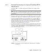
Page 88: ...The external terminator is necessary only during certain maintenance tasks performed with a Sun StorEdge 3310 SCSI JBOD dual bus configuration which is connected directly to multiple servers in a clustering environment most often the Sun Cluster environment With many maintenance tasks you remove a failed or outdated part and replace it immediately this is standard procedure However if you have an ...

Page 89: ...iginal SCSI IDs and correct termination on a dual bus JBOD in a cluster environment insert an external terminator in all cases where a SCSI port becomes empty that was not empty in the original configuration This maintains the SCSI drive IDs for the active host connections For an example of two removed cables and two inserted terminators see FIGURE 6 3 In a dual bus configuration the SCSI IDs chan...

Page 90: ... higher use the information in this section Note The older I O modules only supported single initiator dual bus configurations In a dual bus configuration the SCSI IDs change according to the termination on the SCSI ports If your original configuration has both SCSI ports connected on a bus connected to host s the SCSI IDs are 0 to 5 If only the bottom port is connected to a host the SCSI IDs are ...

Page 91: ... port of the array is disconnected move the cable of the top port to the bottom port The moved cable provides termination to the bottom port 4 Insert the external terminator into the empty top SCSI port on the array The external terminator preserves the original SCSI IDs which are 0 to 5 on each bus that has two host connections established 5 Resume host I O activity on the remaining host s You ca...

Page 92: ...ug cable from port A OUT and move it to port A IN 3 Install a terminator in port A OUT Scenario 2 Disconnect 1 cable from B IN port 1 Disconnect Host 1 cable from port B IN 2 Unplug cable from port B OUT and move it to port B IN 3 Install a terminator in port B OUT Scenario 3 Disconnect 1 cable from A OUT port 1 Disconnect Host 1 cable from port A OUT 2 Install a terminator in port A OUT Scenario ...

Page 93: ...ontroller array to a single controller array The filler panel protects the interior of the array To install a filler panel perform the following steps 1 Remove the controller module according to Removing a SCSI Controller Module on page 6 2 2 Position the filler panel so that it covers the empty slot and the thumbscrews overlay the thumbscrew holes 3 Turn the thumbscrews on the left and right side...

Page 94: ...6 20 Sun StorEdge 3000 Family FRU Installation Guide May 2004 ...

Page 95: ...ansion Chassis FRU The Sun StorEdge 3120 SCSI array box FRU includes a chassis its drive midplane and its backplane This product is ordered to replace a box that has been damaged or whose midplane backplane or terminator module has been damaged To make a fully functional array you need to add the following parts from the replaced array Drive modules Two power supply fan modules To install the indi...

Page 96: ...s 12 13 14 and 15 5 Remove all SCSI cables attached to the I O module 6 Label each disk drive with its disk slot position in the array 7 Remove the power supply modules and disk drives from the defective array 8 Remove the defective chassis 9 Obtain the replacement chassis 10 Re install all previously removed modules in their original positions into the replacement array 11 Re install all SCSI and...

Reviews: