6-12
Sun Blade 100 Service Manual • October 2000
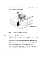
c. Slide the peripheral assembly back and lift it from the chassis. Do not remove
any of the cables attached to the peripheral assembly.
d. Set the peripheral assembly on an antistatic mat.
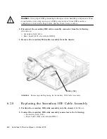
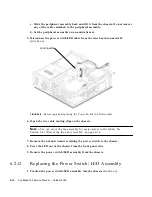
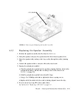
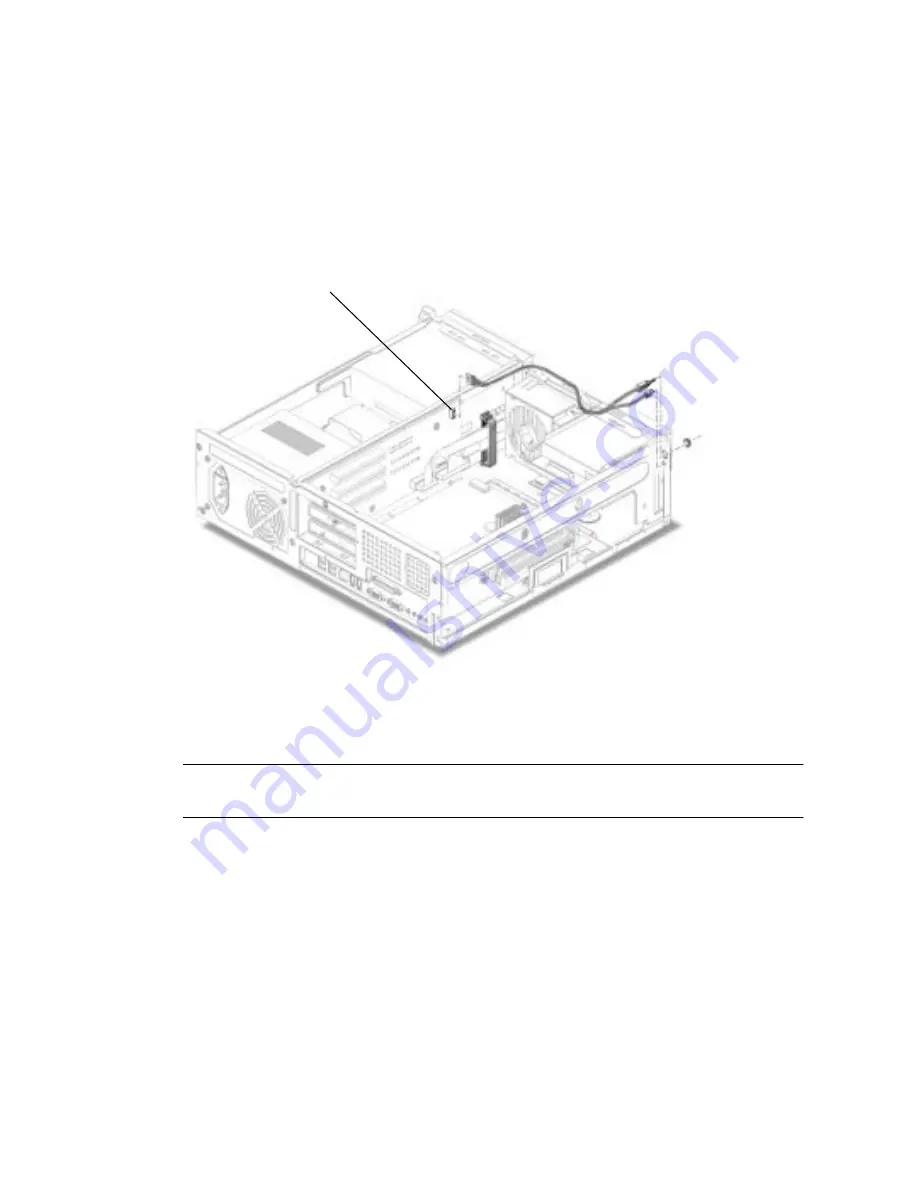
5. Disconnect the power switch/LED cable from the riser board connector J2
(
FIGURE 6-8
).
FIGURE 6-8
Removing and Replacing the Power Switch/LED Assembly
6. Open the two cable routing clips on the chassis.
Note –
You can move the fan assembly for easier access to the cables. See
Section 6.4.1 “Removing the Fan Assembly” on page 6-16.
7. Remove the nut and washer retaining the power switch to the chassis.
8. Press the LED out of the chassis from the front panel side.
9. Remove the power switch/LED assembly from the chassis.
6.2.12
Replacing the Power Switch/LED Assembly
1. Position the power switch/LED assembly into the chassis (
FIGURE 6-8
).
J2 connector
Summary of Contents for Sun Blade 100
Page 6: ...vi Sun Blade 1000 Service Manual September 2000...
Page 8: ...viii Sun Blade 100 Service Manual October 2000...
Page 26: ...xxvi Sun Blade 100 Service Manual October 2000...
Page 30: ...xxx Sun Blade 100 Service Manual October 2000...
Page 38: ...xxxviii Sun Blade 100 Service Manual October 2000...
Page 40: ...1 2 Sun Blade 100 Service Manual October 2000 FIGURE 1 1 Sun Blade 100 System...
Page 48: ...1 10 Sun Blade 100 Service Manual October 2000...
Page 52: ...2 4 Sun Blade 100 Service Manual October 2000...
Page 94: ...4 26 Sun Blade 100 Service Manual October 2000...
Page 102: ...5 8 Sun Blade 100 Service Manual October 2000...
Page 120: ...6 18 Sun Blade 100 Service Manual October 2000...
Page 154: ...8 22 Sun Blade 100 Service Manual October 2000...
Page 158: ...9 4 Sun Blade 100 Service Manual October 2000...
Page 162: ...10 8 Sun Blade 100 Service Manual October 2000...
Page 170: ...A 8 Sun Grover Service Manual October 2000...


