Chapter 11
Replacing the Motherboard and Associated Components
11-47
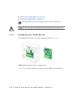
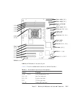
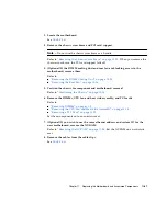
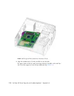
2. Locate the motherboard.
See
.
3. Remove the chassis cross brace and PCI card support.
Note –
Do not use the chassis cross brace as a handle.
Refer to
“Removing the Chassis Cross Brace” on page
. When you remove the
chassis cross brace, the PCI card support falls off.
4. (Optional) If the DIMM cooling duct and rear fan are blocking access to the
motherboard, remove them.
Refer to:
■
“Removing the DIMM Cooling Duct” on page
■
“Removing the Rear Fan” on page
5. Position the chassis for component and motherboard removal.
Refer to
“Positioning the Chassis” on page
6. Remove the DIMMs, CPU fan and heat sink assembly, and PCI cards.
Refer to:
■
■
“Removing the CPU Fan and Heat Sink Assembly” on page
■
Set these components onto an antistatic mat.
7. (Optional) If you wish to use the same ethernet address and system ID for the
new motherboard, remove the NVRAM.
Refer to
. Set the NVRAM on an antistatic
mat.
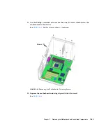
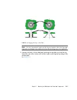
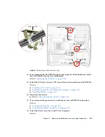
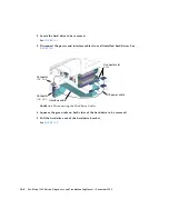
8. Remove the cables from the cable clips.
See
.
Summary of Contents for Sun Blade 1500
Page 16: ...xvi Sun Blade 1500 Service Diagnostics and Troubleshooting Manual December 2004...
Page 30: ...xxx Sun Blade 1500 Service Diagnostics and Troubleshooting Manual December 2004...
Page 40: ...xl Sun Blade 1500 Service Diagnostics and Troubleshooting Manual December 2004...
Page 186: ...8 22 Sun Blade 1500 Service Diagnostics and Troubleshooting Manual December 2004...
Page 360: ...13 62 Sun Blade 1500 Service Diagnostics and Troubleshooting Manual December 2004...
Page 412: ...A 4 Sun Blade 1500 Service Diagnostics and Troubleshooting Manual December 2004...
Page 432: ...B 20 Sun Blade 1500 Service Diagnostics and Troubleshooting Manual December 2004...
Page 472: ...C 40 Sun Blade 1500 Service Diagnostics and Troubleshooting Manual December 2004...
Page 500: ...Index 14 Sun Blade 1500 Service Diagnostics and Troubleshooting Manual December 2004...


