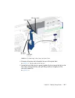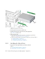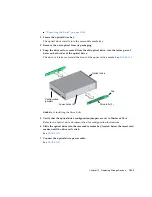
11-56
Sun Blade 1500 Service, Diagnostics, and Troubleshooting Manual
• December
2004
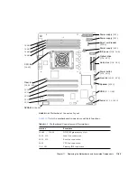
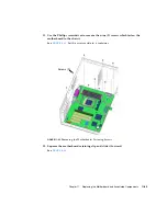
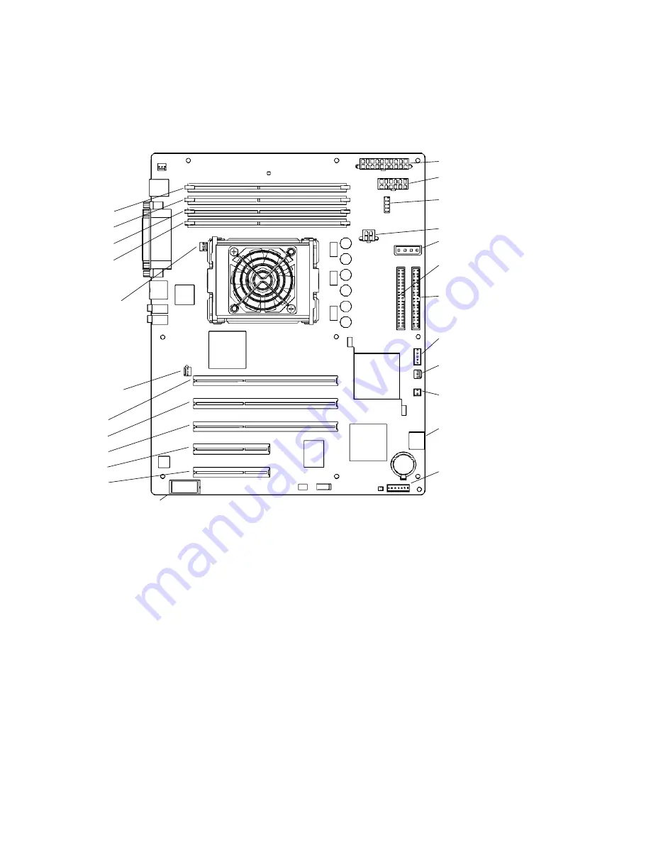
FIGURE
11-51
Motherboard Connectors
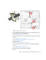
12. Connect the power and signal cables to the corresponding component connector:
■
Power supply cables at connectors
PS0
,
PS1
, and
PS2
■
IDE power at connector
IDE PWR
■
Power button at connector
J24 SW0
■
Front fan at connector
FAN0 SYS
■
Rear fan at connector
FAN1 SYS
(if the rear fan was not removed)
■
Front audio at connector
J13 AUDIO
■
Speaker at connector
SPK0
13. Secure the cables into the cable clips.
See
.
Power supply (
PS2
)
Power supply (
PS1
)
IDE power (
IDE PWR
)
Smart card reader
(
SCR0
)
Optical drive
Hard drive (
IDE PRI
)
(
IDE SEC
)
Power button
Front fan (
FAN0 SYS
)
Speaker (
SPK0
)
Audio (
J13 AUDIO
)
USB (
J19 USB
)
Rear fan
(
FAN1 SYS
)
PCI4
PCI3
PCI2
PCI1
PCI0
DIMM3
DIMM2
DIMM1
DIMM0
Power supply (
PS0
)
CPU fan
(
FAN2
)
(
J24 SW0
)
NVRAM (
NVRAM0
)
Summary of Contents for Sun Blade 1500
Page 16: ...xvi Sun Blade 1500 Service Diagnostics and Troubleshooting Manual December 2004...
Page 30: ...xxx Sun Blade 1500 Service Diagnostics and Troubleshooting Manual December 2004...
Page 40: ...xl Sun Blade 1500 Service Diagnostics and Troubleshooting Manual December 2004...
Page 186: ...8 22 Sun Blade 1500 Service Diagnostics and Troubleshooting Manual December 2004...
Page 360: ...13 62 Sun Blade 1500 Service Diagnostics and Troubleshooting Manual December 2004...
Page 412: ...A 4 Sun Blade 1500 Service Diagnostics and Troubleshooting Manual December 2004...
Page 432: ...B 20 Sun Blade 1500 Service Diagnostics and Troubleshooting Manual December 2004...
Page 472: ...C 40 Sun Blade 1500 Service Diagnostics and Troubleshooting Manual December 2004...
Page 500: ...Index 14 Sun Blade 1500 Service Diagnostics and Troubleshooting Manual December 2004...


