13-2
Sun Blade 1500 Service, Diagnostics, and Troubleshooting Manual
• December
2004
Caution –
When servicing or removing workstation components, attach an
antistatic strap to your wrist and then to a metal area on the chassis. Then disconnect
the power cord from the workstation and the wall receptacle. Following this caution
equalizes all electrical potentials with the workstation.
13.1
Replacing the Power Supply
This section describes removal and installation of the power supply. Topics include:
■
“Identifying the Power Supply” on page
■
“Removing the Power Supply” on page
■
“Installing the Power Supply” on page
Click this film icon to view an animated version of these instructions.
13.1.1
Identifying the Power Supply
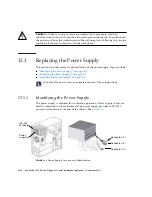
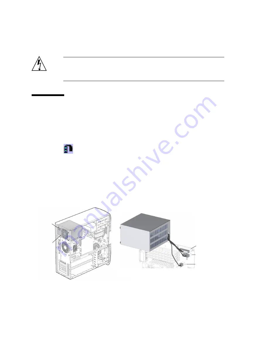
The power supply is required for workstation operation. Power supply cables are
directly connected to the motherboard. The power supply provides an IEC-320
power cord connector at the rear of the chassis. See
FIGURE
13-1
Power Supply Location and Identification
Connector
PS2
Connector
PS1
Connector
PS0
IEC-320
Power
connector
supply fan
Summary of Contents for Sun Blade 1500
Page 16: ...xvi Sun Blade 1500 Service Diagnostics and Troubleshooting Manual December 2004...
Page 30: ...xxx Sun Blade 1500 Service Diagnostics and Troubleshooting Manual December 2004...
Page 40: ...xl Sun Blade 1500 Service Diagnostics and Troubleshooting Manual December 2004...
Page 186: ...8 22 Sun Blade 1500 Service Diagnostics and Troubleshooting Manual December 2004...
Page 360: ...13 62 Sun Blade 1500 Service Diagnostics and Troubleshooting Manual December 2004...
Page 412: ...A 4 Sun Blade 1500 Service Diagnostics and Troubleshooting Manual December 2004...
Page 432: ...B 20 Sun Blade 1500 Service Diagnostics and Troubleshooting Manual December 2004...
Page 472: ...C 40 Sun Blade 1500 Service Diagnostics and Troubleshooting Manual December 2004...
Page 500: ...Index 14 Sun Blade 1500 Service Diagnostics and Troubleshooting Manual December 2004...

