Chapter 13
Replacing Chassis Components
13-5
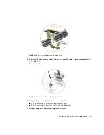
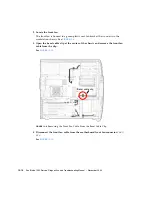
5. Using a No. 2 Phillips screwdriver, remove the three screws that secure the power
supply to the rear panel of the chassis.
See
. Set the screws aside in a container.
FIGURE
13-4
Removing Power Supply.
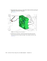
6. Rotate the rear of the power supply slightly outward, then lift the power supply
up and out of the chassis.
See
. Set the power supply aside on an antistatic mat.
Proceed to
“Installing the Power Supply” on page
Note –
The workstation cannot operate without the power supply.
13.1.3
Installing the Power Supply
1. Open and position the chassis.
Refer to:
■
“Removing the Access Panel” on page
■
“Positioning the Chassis” on page
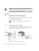
Screws (3)
Power supply
Connectors
PS0
,
PS1
,
PS2
IEC-320
connector
Power supply
fan
Summary of Contents for Sun Blade 1500
Page 16: ...xvi Sun Blade 1500 Service Diagnostics and Troubleshooting Manual December 2004...
Page 30: ...xxx Sun Blade 1500 Service Diagnostics and Troubleshooting Manual December 2004...
Page 40: ...xl Sun Blade 1500 Service Diagnostics and Troubleshooting Manual December 2004...
Page 186: ...8 22 Sun Blade 1500 Service Diagnostics and Troubleshooting Manual December 2004...
Page 360: ...13 62 Sun Blade 1500 Service Diagnostics and Troubleshooting Manual December 2004...
Page 412: ...A 4 Sun Blade 1500 Service Diagnostics and Troubleshooting Manual December 2004...
Page 432: ...B 20 Sun Blade 1500 Service Diagnostics and Troubleshooting Manual December 2004...
Page 472: ...C 40 Sun Blade 1500 Service Diagnostics and Troubleshooting Manual December 2004...
Page 500: ...Index 14 Sun Blade 1500 Service Diagnostics and Troubleshooting Manual December 2004...


