Chapter 13
Replacing Chassis Components
13-7
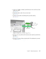
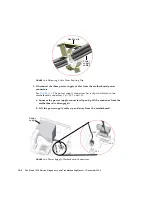
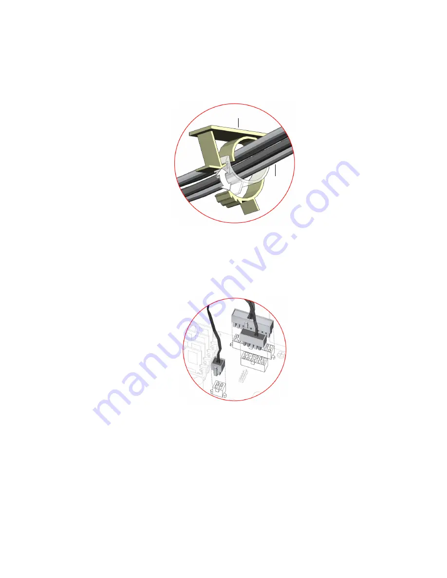
FIGURE
13-6
Securing Cables Into Routing Clips
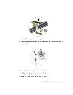
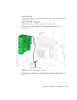
9. Connect the three power supply cables to the motherboard power connectors
PS0
,
PS1
, and
PS2
.
See
FIGURE
13-7
Attaching Power Supply Connectors
10. Inspect the power supply fasteners to verify that:
■
The power supply screws are in place and tight.
■
The power supply is well seated in the chassis guides.
11. Inspect the power supply cabling to verify that:
Routing clip
Power
supply
cables
PS0
PS1
PS2
Summary of Contents for Sun Blade 1500
Page 16: ...xvi Sun Blade 1500 Service Diagnostics and Troubleshooting Manual December 2004...
Page 30: ...xxx Sun Blade 1500 Service Diagnostics and Troubleshooting Manual December 2004...
Page 40: ...xl Sun Blade 1500 Service Diagnostics and Troubleshooting Manual December 2004...
Page 186: ...8 22 Sun Blade 1500 Service Diagnostics and Troubleshooting Manual December 2004...
Page 360: ...13 62 Sun Blade 1500 Service Diagnostics and Troubleshooting Manual December 2004...
Page 412: ...A 4 Sun Blade 1500 Service Diagnostics and Troubleshooting Manual December 2004...
Page 432: ...B 20 Sun Blade 1500 Service Diagnostics and Troubleshooting Manual December 2004...
Page 472: ...C 40 Sun Blade 1500 Service Diagnostics and Troubleshooting Manual December 2004...
Page 500: ...Index 14 Sun Blade 1500 Service Diagnostics and Troubleshooting Manual December 2004...


