Chapter 14
Replacing Internal Cables
14-23
■
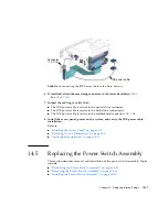
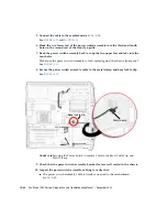
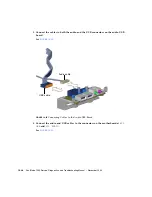
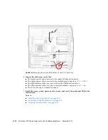
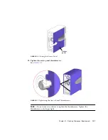
The power switch assembly cable is secure in the metal clamp and bezel cable
clip.
11. Install the bezel, the access panel, power on the system, and verify the power
switch assembly installation.
Refer to:
■
“Installing the Bezel” on page
■
“Installing the Access Panel” on page
■
“Powering On the Workstation” on page
■
“Verifying an Installation” on page
14.6
Replacing the Audio USB Board Cables
This section describes removal and installation of the audio USB board interface
cables. Topics include:
■
“Identifying the Audio USB Board Cables” on page
■
“Removing the Audio USB Board Cables” on page
■
“Installing the Audio USB Board Cables” on page
14.6.1
Identifying the Audio USB Board Cables
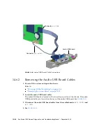
The audio USB board has two separate cable sets, one for audio and one for USB.
The audio signals are carried by three shielded multi-conductor cables connecting to
the motherboard at
J13 AUDIO
. The USB interface cable is a 10-conductor ribbon
cable connecting at
J19 USB
.
shows the audio USB board cable
connections.
Summary of Contents for Sun Blade 1500
Page 16: ...xvi Sun Blade 1500 Service Diagnostics and Troubleshooting Manual December 2004...
Page 30: ...xxx Sun Blade 1500 Service Diagnostics and Troubleshooting Manual December 2004...
Page 40: ...xl Sun Blade 1500 Service Diagnostics and Troubleshooting Manual December 2004...
Page 186: ...8 22 Sun Blade 1500 Service Diagnostics and Troubleshooting Manual December 2004...
Page 360: ...13 62 Sun Blade 1500 Service Diagnostics and Troubleshooting Manual December 2004...
Page 412: ...A 4 Sun Blade 1500 Service Diagnostics and Troubleshooting Manual December 2004...
Page 432: ...B 20 Sun Blade 1500 Service Diagnostics and Troubleshooting Manual December 2004...
Page 472: ...C 40 Sun Blade 1500 Service Diagnostics and Troubleshooting Manual December 2004...
Page 500: ...Index 14 Sun Blade 1500 Service Diagnostics and Troubleshooting Manual December 2004...


