Appendix B
Signal
Descriptions
B-11
More information about attaching a stereoscopic imager is available in the
Sun XVR-
600 Graphics Accelerator Installation and User’s Guide
, 817-2195 or the
Sun XVR-1200
Graphics Accelerator Installation and User’s Guide
, 816-7386.
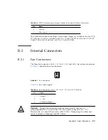
B.2
Internal Connectors
B.2.1
Fan Connectors
The three fan connectors,
FAN0 SYS
,
FAN1 SYS
, and
FAN2
, have the same pinouts.
identifies these fan connectors.
FIGURE
B-7
Fan Connector
lists these signals.
Caution –
Though the connectors have the same pinouts, they are
not
interchangeable. Do
not
connect the CPU fan cable to connector
FAN1 SYS
.
Similarly, do
not
connect the rear fan cable to
FAN2
. Transposing the cables may
result in system overheating and CPU failure.
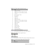
8
Ground
9
Done input
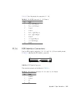
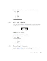
TABLE
B-15
Fan Connectors
FAN0 SYS
,
FAN1 SYS
, and
FAN2
Pinouts
Pin
Signal
1
Ground
2
8 - 12 V
3
Tachometer Signal
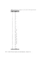
TABLE
B-14
DB-9 In Stereoscopic Imager Interface Connector Pinouts
(Continued)
Pin
Signal
3
2
1
Summary of Contents for Sun Blade 1500
Page 16: ...xvi Sun Blade 1500 Service Diagnostics and Troubleshooting Manual December 2004...
Page 30: ...xxx Sun Blade 1500 Service Diagnostics and Troubleshooting Manual December 2004...
Page 40: ...xl Sun Blade 1500 Service Diagnostics and Troubleshooting Manual December 2004...
Page 186: ...8 22 Sun Blade 1500 Service Diagnostics and Troubleshooting Manual December 2004...
Page 360: ...13 62 Sun Blade 1500 Service Diagnostics and Troubleshooting Manual December 2004...
Page 412: ...A 4 Sun Blade 1500 Service Diagnostics and Troubleshooting Manual December 2004...
Page 432: ...B 20 Sun Blade 1500 Service Diagnostics and Troubleshooting Manual December 2004...
Page 472: ...C 40 Sun Blade 1500 Service Diagnostics and Troubleshooting Manual December 2004...
Page 500: ...Index 14 Sun Blade 1500 Service Diagnostics and Troubleshooting Manual December 2004...

