background image

Chapter 3

 Basic 

Troubleshooting 


3-25

3.3.5

ping

 Command

The 

ping

 command sends ICMP ECHO_REQUEST packets to network hosts. 

Depending upon how the 

ping

 command is configured, the output displayed can 

identify troublesome network links or nodes. The destination host is specified in the 
variable 

hostname

.

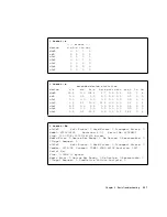
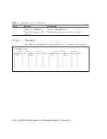
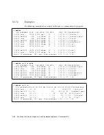
netstat -p

Net to Media Table: IPv4

Device   IP Address               Mask      Flags   Phys Addr 

------ -------------------- --------------- ----- ---------------

bge0   phatair-46           255.255.255.255       08:00:20:92:4a:47

bge0   ns-umpk27-02-46      255.255.255.255       08:00:20:93:fb:99

bge0   moreair-46           255.255.255.255       08:00:20:8a:e5:03

bge0   fermpk28a-46         255.255.255.255       00:00:0c:07:ac:2e

bge0   fermpk28as-46        255.255.255.255       00:50:e2:61:d8:00

bge0   kayakr               255.255.255.255       08:00:20:d1:83:c7

bge0   matlock              255.255.255.255 SP    00:03:ba:27:01:48

bge0   toronto2             255.255.255.255       08:00:20:b6:15:b5

bge0   tucknott             255.255.255.255       08:00:20:7c:f5:94

bge0   mpk28-lobby          255.255.255.255       08:00:20:a6:d5:c8

bge0   eggfooyoung          255.255.255.255       08:00:20:8d:6a:80

bge0   froggy               255.255.255.255       08:00:20:73:70:44

bge0   d-mpk28-46-245       255.255.255.255       00:10:60:24:0e:00

bge0   224.0.0.0            240.0.0.0       SM    01:00:5e:00:00:00

netstat -r

Routing Table: IPv4

  Destination           Gateway           Flags  Ref   Use   Interface

-------------------- -------------------- ----- ----- ------ ---------

mpk28-046-n          matlock               U        1      6  bge0

224.0.0.0            matlock               U        1      0  bge0

default              fermpk28a-46          UG       1     22  

localhost            localhost             UH      25   3018  lo0

Summary of Contents for Sun Blade 1500

Page 1: ...ems Inc www sun com Submit comments about this document at http www sun com hwdocs feedback Sun Blade 1500 Service Diagnostics and Troubleshooting Manual Silver Silver Part No 817 5127 11 December 200...

Page 2: ...pyright 2004 Sun Microsystems Inc 4150 Network Circle Santa Clara California 95054 Etats Unis Tous droits r serv s Sun Microsystems Inc a les droits de propri t intellectuels relatants la technologie...

Page 3: ...2 1 Product Overview 2 1 2 2 External System Description 2 3 2 3 Replaceable Components 2 7 2 4 Supported Sun Monitors 2 10 3 Basic Troubleshooting 3 1 3 1 Power On Sequence 3 1 3 2 Display and Audio...

Page 4: ...rd Drive Problem 4 8 4 2 3 System Fan Problem 4 9 4 2 4 USB Problem 4 10 4 2 5 Audio Output Problem 4 12 4 2 6 Monitor Problem 4 14 4 2 7 Network Problem 4 17 4 2 8 Keyboard Problem 4 19 4 2 9 Login P...

Page 5: ...verview 5 5 5 5 2 OpenBoot Diagnostics 5 6 5 6 SunVTS Software 5 6 5 6 1 SunVTS Overview 5 6 5 6 2 SunVTS Requirements 5 6 5 6 3 SunVTS Documentation 5 7 5 7 Sun Install Check 5 7 5 7 1 Sun Install Ch...

Page 6: ...to Boot 7 3 7 2 3 Obtain the ok Prompt 7 4 7 2 4 Configure an External Display Device 7 4 7 2 5 Run POST 7 6 7 3 POST Output 7 6 7 3 1 post min min 7 7 7 3 2 post min normal 7 7 7 3 3 post min max 7 8...

Page 7: ...unVTS 9 1 9 1 Installing SunVTS 9 1 9 2 Exercising System Components Using SunVTS Software 9 1 9 2 1 Connection Mode 9 2 9 2 2 Connection Mode Component Testing 9 2 9 2 3 Functional Mode 9 6 9 2 4 Fun...

Page 8: ...the CPU Fan and Heat Sink Assembly 11 13 11 2 1 Identifying the CPU Fan and Heat Sink Assembly 11 13 11 2 2 Removing the CPU Fan and Heat Sink Assembly 11 14 11 2 3 Installing the CPU Fan and Heat Si...

Page 9: ...ifying the Optical Drive 12 10 12 2 2 Removing the Optical Drive 12 10 12 2 3 Installing the Optical Drive 12 12 12 3 Replacing the Smart Card Reader 12 15 12 3 1 Identifying the Smart Card Reader 12...

Page 10: ...Board 13 31 13 5 3 Installing the Audio USB Board 13 35 13 6 Replacing the Speaker 13 39 13 6 1 Identifying the Speaker 13 39 13 6 2 Removing the Speaker 13 40 13 6 3 Installing the Speaker 13 42 13...

Page 11: ...3 2 Removing the Hard Drive Interface Cable 14 11 14 3 3 Installing the Hard Drive Interface Cable 14 12 14 4 Replacing the IDE Power Cable 14 13 14 4 1 Identifying the IDE Power Cable 14 13 14 4 2 R...

Page 12: ...t Upgrades 16 4 16 3 External Peripherals 16 5 A Product Specifications A 1 A 1 Physical Specifications A 1 A 2 Electrical Specifications A 2 A 3 Acoustic Specifications A 2 A 4 Environmental Requirem...

Page 13: ...nt Overview C 1 C 1 2 System Block Diagram C 3 C 1 3 Enclosure C 3 C 2 Motherboard C 4 C 2 1 Motherboard Block Diagram C 4 C 2 2 Motherboard Layout Diagram C 5 C 2 3 Motherboard Jumpers C 8 C 3 CPU an...

Page 14: ...C 30 C 7 External Interfaces C 31 C 7 1 ATA 100 C 32 C 7 2 Smart Card Reader C 32 C 7 3 USB C 33 C 7 4 Audio C 33 C 7 5 PCI Slots C 33 C 7 6 IEEE 1394 USB 2 Combination Card C 34 C 7 7 Ethernet C 34 C...

Page 15: ...Example Configuration D 4 D 2 2 Activating the Workstation From Low Power Mode D 5 D 3 Disabling Power Management D 5 D 3 1 Disabling Hard Drive Power Management D 5 D 3 2 Disabling All System Power...

Page 16: ...xvi Sun Blade 1500 Service Diagnostics and Troubleshooting Manual December 2004...

Page 17: ...ion 2 10 TABLE 3 1 Screen Images and What They Mean 3 2 TABLE 3 2 OpenBoot PROM Messages and Their Meaning 3 6 TABLE 3 3 Solaris Error Messages and Their Meanings 3 8 TABLE 3 4 Other Messages and Thei...

Page 18: ...BLE 7 5 post min max Output Comparison 7 8 TABLE 7 6 post max normal Output Comparison 7 12 TABLE 7 7 post max max Output Comparison 7 13 TABLE 8 1 OpenBoot Diagnostics Test Usage 8 9 TABLE 9 1 Subseq...

Page 19: ...inouts B 2 TABLE B 2 IEEE 1394A Port Pinouts B 2 TABLE B 3 Parallel Port Pinouts B 3 TABLE B 4 Serial Port Pinouts B 4 TABLE B 5 Twisted Pair Ethernet Port Pinouts B 5 TABLE B 6 Twisted Pair Ethernet...

Page 20: ...t Motherboard Jumper Settings C 8 TABLE C 3 Sun Blade 1500 Supported DIMM Configurations C 13 TABLE C 4 Interleaving Modes C 14 TABLE C 5 Sun XVR 600 Graphics Accelerator Monitor Screen Resolutions C...

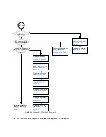
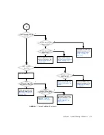
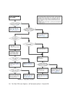
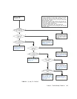
Page 21: ...ges Flowchart 3 6 FIGURE 4 1 Power On Flowchart 4 3 FIGURE 4 2 Power On Flowchart Continued 4 4 FIGURE 4 3 Power Problem 4 6 FIGURE 4 4 Power Problem Continued 4 7 FIGURE 4 5 Hard Drive Problem 4 8 FI...

Page 22: ...7 IEEE 1394 Problem Continued 4 31 FIGURE 4 28 Smart Card Reader Problem 4 32 FIGURE 4 29 Motherboard Problem 4 34 FIGURE 4 30 Motherboard Problem Continued 4 35 FIGURE 4 31 Motherboard Problem Contin...

Page 23: ...11 11 Ejector Levers Closed Position 11 10 FIGURE 11 12 Sliding the Duct Down 11 11 FIGURE 11 13 Examples of Faulty DIMM Locations 11 13 FIGURE 11 14 CPU Fan and Heat Sink Assembly Location and Identi...

Page 24: ...FIGURE 11 39 Installing the PCI Card 11 41 FIGURE 11 40 Fastening the PCI Card Retainer 11 42 FIGURE 11 41 Closing the PCI Card Support 11 43 FIGURE 11 42 Motherboard Location and Identification 11 44...

Page 25: ...17 Removing Smart Card Reader Interface Cable 12 19 FIGURE 12 18 Installing Smart Card Reader Into Bracket 12 20 FIGURE 12 19 Feeding Smart Card Cable Through Chassis 12 21 FIGURE 12 20 Connecting the...

Page 26: ...to the Right 13 26 FIGURE 13 26 Pulling the Duct Free 13 26 FIGURE 13 27 Aligning the Pivot Pins With the Gap 13 27 FIGURE 13 28 Moving the Duct to the Left 13 28 FIGURE 13 29 Swinging the Duct In 13...

Page 27: ...ng Chassis Cross Brace Into Position 13 55 FIGURE 13 58 Preventing PCI Shield From Striking Components 13 56 FIGURE 13 59 Preventing PCI Shield From Binding With Socket 13 57 FIGURE 13 60 PCI Shield F...

Page 28: ...ble to the Bezel Cable Clip and Metal Clamp 14 22 FIGURE 14 21 Audio USB Board Cable Connections 14 24 FIGURE 14 22 Removing Audio and USB Cables From the Motherboard 14 25 FIGURE 14 23 Removing the A...

Page 29: ...face Connector B 13 FIGURE B 11 IDE Power Connector B 15 FIGURE B 12 Power Supply Connectors B 16 FIGURE B 13 Power Switch Connector B 18 FIGURE B 14 Smart Card Reader Connector B 18 FIGURE B 15 Speak...

Page 30: ...xxx Sun Blade 1500 Service Diagnostics and Troubleshooting Manual December 2004...

Page 31: ...ting Manual 816 7564 This manual is written for technicians service personnel and system administrators who service and repair computer systems The person qualified to use this manual Can open a syste...

Page 32: ...nk to Multimedia Instructions Clicking on the above link displays a guided tour of the Sun Blade 1500 workstation How This Book Is Organized Chapter 1 explains how to use the flowcharts in this manual...

Page 33: ...n Blade 1500 workstation Appendix B outlines the external signal descriptions Appendix C provides a functional description of the Sun Blade 1500 workstation Appendix D describes how to manage power sa...

Page 34: ...in the packing carton for the Sun Blade 1500 workstation The Sun Blade 1500 workstation complies with regulatory requirements of safety and EMI as documented in the Sun Blade 1500 Safety and Complian...

Page 35: ...login file Use ls a to list all files You have mail AaBbCc123 What you type when contrasted with on screen computer output su Password AaBbCc123 Book titles new words or terms words to be emphasized R...

Page 36: ...17 5125 Preinstalled software Sun Blade 1500 Getting Started Guide 817 5129 Last minute information Sun Blade 1500 Product Notes 817 5131 Safety and compliance Sun Blade 1500 Safety and Compliance Gui...

Page 37: ...nal Support Resources Sun Blade 1500 Support Resources URL or Telephone Number Find Solaris and other software documents here This is also an alternative web site for some Sun Blade 1500 documents Thi...

Page 38: ...print or purchase a broad selection of Sun documentation including localized versions at http www sun com documentation Contacting Sun Technical Support If you have technical questions about this prod...

Page 39: ...Preface xxxix Please include the title and part number of your document with your feedback Sun Blade 1500 Service Diagnostics and Troubleshooting Manual part number 817 5127 11...

Page 40: ...xl Sun Blade 1500 Service Diagnostics and Troubleshooting Manual December 2004...

Page 41: ...4 1 1 Diagnostic Tools Available The Sun Blade 1500 Service Diagnostic and Troubleshooting Manual uses displayed messages system sounds flowcharts and firmware and software diagnostic tools to help y...

Page 42: ...n configure the OpenBoot PROM for diagnostics and automatic execution of scripts See NVRAM on page 6 1 POST diagnostics Firmware Tests workstation core components such as CPU and memory Checks low lev...

Page 43: ...a problem Plain text states an action Rectangle at the top right of the flowchart Text describes normal operation or provides details about normal conditions Rectangle drawn with bold lines Text gives...

Page 44: ...sic Troubleshoot ing on page 3 1 See Preparing to Replace Components on page 10 1 See Customizing Your System on page 16 1 Is something wrong with the system Y N Do you want to replace a component Y N...

Page 45: ...tasks Examples of these tasks range from entry level 2D graphics EDA applications to mid range 3D graphics MCAD applications Combined with the power of the Solaris operating system Sun Blade 1500 work...

Page 46: ...imum of 8 GB of ECC error correcting DDR 1 SDRAM memory using matched pairs of 512 MB 1 GB or 2 GB DIMMs Maximum of 2 DIMM pairs per system 4 DIMMS total Power supply 420 W autoranging Internal storag...

Page 47: ...x00 and D1000 hard drive arrays Sun StorEdge L1000 and L11000 tape drive arrays 2 2 External System Description FIGURE 2 1 FIGURE 2 2 and FIGURE 2 3 identify external components and connectors of the...

Page 48: ...l December 2004 FIGURE 2 1 Monitor Keyboard Mouse and Sun Blade 1500 Workstation Note Make sure that the keyboard and mouse are only connected to USB 1 1 compliant connectors on the bezel or rear pane...

Page 49: ...00 Workstation TABLE 2 2 Bezel Overview Sun Blade 1500 Workstation Callout in FIGURE 2 2 Part Description Bezel Symbol 1 Smart card reader LED none 2 Smart card reader none 3 Optical drive none 4 Opti...

Page 50: ...Rear Panel Overview Sun Blade 1500 Workstation 6 Power button with LED 7 USB v1 1 connector 2 8 Audio connector headphone 9 Audio connector microphone TABLE 2 2 Bezel Overview Sun Blade 1500 Workstat...

Page 51: ...lout in FIGURE 2 3 Part Description Rear Panel Symbol A Power connector none B USB v1 1 connector 2 C Serial1 connector DB 9 D Parallel connector DB 25 E Serial2 connector DB 9 F Twisted pair Ethernet...

Page 52: ...f Sun Blade 1500 Replaceable Components More information about the replaceable components is listed in TABLE 2 4 TABLE 2 4 Sun Blade 1500 Replaceable Components Callout in FIGURE 2 4 Component Descrip...

Page 53: ...ront fan Front fan Sun Blade 1500 chassis 12VDC 6 Rear fan Rear fan Sun Blade 1500 chassis 12VDC 7 Smart card reader Smart card reader bare board 8 Audio USB board USB connector board mounting bracket...

Page 54: ...hics accelerators refer to the Sun XVR 100 Graphics Accelerator Installation Guide 816 7560 the Sun XVR 600 Graphics Accelerator Installation and User s Guide 817 2195 or the Sun XVR 1200 Graphics Acc...

Page 55: ...equence of power on events that occur before a user can interact with the Sun Blade 1500 workstation 1 Power button is pressed 2 OpenBoot PROM initiates system power on reset SPOR 3 OpenBoot PROM init...

Page 56: ...can often be diagnosed by looking at the monitor or listening to the system Topics in this section include Displayed Screens on page 3 2 Displayed Messages on page 3 5 Audio Responses on page 3 12 3...

Page 57: ...blem on page 4 28 GUI is too small too large or not centered Monitor settings or sync problem Adjust monitor according to monitor manual Verify monitor can sync to set frequency See Graphics Accelerat...

Page 58: ...4 28 GUI is in wrong language Locale problem 1 Log out 2 At the login GUI Options pulldown select Language 3 Select your language 4 Log in as usual Window in GUI is completely white Window process is...

Page 59: ...le addresses the error message you see Display is black with hourglass Network problem See Network Problem on page 4 17 Dtlogin problem See Login Problem on page 4 20 Display is black with mouse point...

Page 60: ...he battery has drained Replace the battery See Replacing the Battery on page 11 22 See Displayed Screens on page 3 2 An error message is dis played on the system s monitor See Solaris Error Mes sages...

Page 61: ...NOTICE CPUx Banky DIMMs have different architectures and will not be used A pair of DIMMs are each of different architectures The DIMMs are not used Install DIMMs in identical pairs See Replacing the...

Page 62: ...d address The value of an address is invalid Determine and use the correct address Bad file number A program error where the application does not have permission to interact with the file Program bug...

Page 63: ...te a file occurred Rename or remove the existing file File name too long A file name was greater than 256 characters or a path name was over 1024 characters If more characters are required edit the us...

Page 64: ...There is no route to network or gateways are refusing packets Check network security NFS read failed for server File sharing permissions changed while the file was open Close the file and reset the p...

Page 65: ...lient was removed from or permissions changed on the NFS server Reboot the NFS client TABLE 3 4 Other Messages and Their Meaning Message Meaning What to do Panic in kernel The Solaris kernel can no lo...

Page 66: ...roblem if system does not boot and message persists Check network See Network Problem on page 4 17 Check time server The X server can not be started on display 0 The GUI cannot be started for certain...

Page 67: ...age 4 28 Very high pitched whine Monitor cannot sync Change graphics accelerator resolution See graphics accelerator documentation See Monitor Problem on page 4 14 See PCI Card Problem on page 4 28 Mo...

Page 68: ...ng hard drive heads are moving Hard drive is normal High pitched humming hard drive bearings are failing Replace the hard drive See Replacing a Hard Drive on page 12 2 Front or rear of system chassis...

Page 69: ...ive and tape I O activity as well as CPU utilization Optical drive Repetitive quiet clunking Disc is unbalanced Reposition disc Rapid shifting Laser pickup head is moving Optical drive normal Rushing...

Page 70: ...device error summary statistics The total errors hard errors soft errors and transport errors are displayed Provides a short table with accumulated errors Identifies suspect I O devices E Displays al...

Page 71: ...9 3 0 2 nfs3 0 2 0 0 0 9 0 0 0 0 0 0 2 5 0 0 nfs4 0 0 0 0 0 0 0 0 0 0 0 0 0 0 0 0 nfs5 1 5 0 0 30 2 0 0 0 0 0 1 38 6 0 4 iostat En c0t0d0 Soft Errors 0 Hard Errors 0 Transport Errors 0 Model ST312002...

Page 72: ...s normal 3 3 2 1 Options TABLE 3 7 describes options for the prtdiag command and how those options can help troubleshoot the Sun Blade 1500 workstation 3 3 2 2 Examples The following examples show out...

Page 73: ...Model pci 33 MB isa su serial okay pci 1e 600000 isa 7 serial 0 3f8 pci 33 MB isa su serial okay pci 1e 600000 isa 7 serial 0 2e8 pci 66 MB pci108e 1647 network okay pci 1f 700000 network 2 pci 66 MB...

Page 74: ...if a driver for the hardware is loaded usr platform sun4u sbin prtdiag v System Configuration Sun Microsystems sun4u Sun Blade 1500 workstation System clock frequency 160 MHZ Memory size 1GB Environme...

Page 75: ...is probably functioning properly If the message driver not attached is displayed for the device or for a sub device then the driver for the device is corrupt or missing D Similar to the output of no...

Page 76: ...ot attached SUNW builtin drivers driver not attached deblocker driver not attached disk label driver not attached terminal emulator driver not attached dropins driver not attached kbd translator drive...

Page 77: ...0 driver name pcf8584 hardware monitor instance 0 driver name adm1031 motherboard fru prom instance 0 driver name seeprom dimm spd instance 1 driver name seeprom dimm spd instance 2 driver name seepr...

Page 78: ...n Replaces host names with IP addresses When an address is more useful than a host name netstat i 1 input bge0 output input Total output packets errs packets errs colls packets errs packets errs colls...

Page 79: ...rmpk28a 46 255 255 255 255 00 00 0c 07 ac 2e bge0 fermpk28as 46 255 255 255 255 00 50 e2 61 d8 00 bge0 kayakr 255 255 255 255 08 00 20 d1 83 c7 bge0 matlock 255 255 255 255 SP 00 03 ba 27 01 48 bge0 t...

Page 80: ...e probe packet through Enables a simple check of secondary network interfaces n Replaces host names with IP addresses Used when an address is more beneficial than a host name s Ping continuously in on...

Page 81: ...k11s10 r02 v827 192 146 5 137 fermpk28ap 46 192 146 46 2 matlock 192 146 46 111 End of record C teddybear PING Statistics 1 packets transmitted 1 packets received 0 packet loss round trip ms min avg m...

Page 82: ...geout root 3 0 0 10 06 32 0 00 fsflush root 100311 1 0 10 06 50 0 00 usr lib saf sac t 300 ps eo pcpu pid comm sort rn 1 4 100317 usr openwin bin Xsun 0 9 100460 dtwm 0 1 100677 ps 0 1 100600 ksh 0 1...

Page 83: ...ption How It Can Help No option Displays a sorted list of the top processes which are consuming the most CPU resources List is limited to the height of the terminal window and the total number of proc...

Page 84: ...ot 1800K 1232K sleep 58 0 0 00 00 0 0 sac 1 Total 65 processes 159 lwps load averages 0 01 0 02 0 04 prstat n 5 s size PID USERNAME SIZE RSS STATE PRI NICE TIME CPU PROCESS NLWP 100524 mm39236 28M 21M...

Page 85: ...Problem on page 4 10 Audio Output Problem on page 4 12 Monitor Problem on page 4 14 Network Problem on page 4 17 Keyboard Problem on page 4 19 Login Problem on page 4 20 Graphical User Interface Probl...

Page 86: ...lade 1500 workstation is at fault If you suspect a system failure power on the system and follow the flowchart If you answer No to a question direct your attention to the section provided or to other...

Page 87: ...with graphics accelerator See PCI Card Problem on page 4 28 Problem with network See Network Problem on page 4 17 Problem with hard drive See Hard Drive Problem on page 4 8 Problem with fan See Syste...

Page 88: ...vers See Data Access and Run ning Applications Prob lems on page 4 23 Problem with optical drive See Optical Drive Problem on page 4 25 Problem with resources See Graphical User Inter face Problem on...

Page 89: ...blem on page 4 6 Hard Drive Problem on page 4 8 System Fan Problem on page 4 9 USB Problem on page 4 10 Audio Output Problem on page 4 12 Monitor Problem on page 4 14 Network Problem on page 4 17 Keyb...

Page 90: ...necessary See Motherboard Problem on page 4 34 Power on system Y N Y N Y N Y N In normal operation the motherboard LED0 glows as standby power is supplied to the workstation You can view the glow from...

Page 91: ...wer Switch Assembly on page 14 17 A Do any system fans spin Does the hard drive spin up Check motherboard and replace if necessary See Motherboard Problem on page 4 34 System fan problem See System Fa...

Page 92: ...A keys Type probe ide Is the manufacturer and model of the suspect hard drive displayed Check the hard drive with OpenBoot Diagnostics See OpenBoot Diagnos tics on page 8 5 Type boot to start the ope...

Page 93: ...inning Check CPU fan and replace if necessary See Replacing the CPU Fan and Heat Sink Assembly on page 11 13 Is the CPU fan exceptionally noisy Replace the front fan See Replacing the Front Fan on pag...

Page 94: ...Power On Flowchart on page 4 3 Is the suspect device a USB 1 0 or USB 1 1 device Y N Y N Go to B In normal operation the USB ports allow for hot plugging of peripherals If the peripheral is not recog...

Page 95: ...Cards on page 11 28 Go to B Replace the combination card See Replacing the PCI Cards on page 11 28 Start the operating sys tem Type ok boot r Determine if the USB ports are recognized Type prtconf B D...

Page 96: ...ace if necessary See Motherboard Problem on page 4 34 Attach the headphones to the audio out jack on the rear panel and run the audio test again Check the audio USB board and replace if nec essary See...

Page 97: ...he headphones Problem with Solaris audio drivers Contact system administrator Problem with audio soft ware application Contact system administrator Check the audio with SunVTS See SunVTS on page 9 1 S...

Page 98: ...nitor key board and mouse directly to workstation Tap spacebar and move mouse Set the brightness and contrast controls to their center positions Is the problem still there Return to Power On Flowchart...

Page 99: ...urn to Power On Flowchart on page 4 3 Turn monitor on Check power require ments See Electrical Specifications on page A 2 Attach known good elec tric device or tester to wall receptacle Resolve facili...

Page 100: ...onnector on the monitor signal cable good Replace monitor signal cable Replace the graphics accelerator See Replac ing the PCI Cards on page 11 28 Does the monitor have a multi input switch Set the sw...

Page 101: ...cables back 2 Replace the system s network cable Did this solve the problem Return to Power On Flowchart on page 4 3 Y N Y N Y N Y N In normal operation the network is invisible to the user When a sy...

Page 102: ...and heath Is the operating system running Is the ok prompt displayed Press the Stop A keys Type watch net all Are packets being read Check motherboard and replace if necessary See Motherboard Problem...

Page 103: ...ck the audio USB board and replace if nec essary See Replacing the Audio USB Board on page 13 30 Connect the keyboard to each USB port and type Is the keyboard functioning properly at the rear panel C...

Page 104: ...oftware problem Contact system adminis trator Return to Power On Flowchart on page 4 3 Can you type a user name and password Check the USB ports See USB Problem on page 4 10 Did this solve the problem...

Page 105: ...the systems s TPE connector flashing Refer to displayed screens table See Displayed Screens on page 3 2 Check the name service Contact system adminis trator Check the network con nection See Network P...

Page 106: ...of the applica tion that is hung Check the network con nection See Network Problem on page 4 17 1 Save information 2 Kill the process 3 Restart the applica tion Return to Power On Flowchart on page 4...

Page 107: ...page 4 3 Diagnose file server or application server Con tact system administra tor Did this solve the problem Did this solve the problem Did this solve the problem Check network hardware and status Re...

Page 108: ...ting Manual December 2004 4 3 Storage Problems The following flowcharts help troubleshoot problems with storage devices Optical Drive Problem on page 4 25 PCI Card Problem on page 4 28 IEEE 1394 Probl...

Page 109: ...tables See Dis played Messages on page 3 5 Is the operating system running Is the ok prompt displayed Press the Stop A keys Stop the volume manager As supe ruser type etc init d volmgt stop Y N Y N Y...

Page 110: ...mgt start Check the optical drive with SunVTS See Sun VTS on page 9 1 Can you read from the optical drive Return to Power On Flowchart on page 4 3 Are the manufacturer and model of the optical drive d...

Page 111: ...ace the optical drive Did you check or replace the optical drive signal or power cable Check the optical drive and replace if necessary See Replacing the Opti cal Drive on page 12 9 Check motherboard...

Page 112: ...oblem still there Check card slot seating See Installing a PCI Card on page 11 38 Check the cable periph eral and card and replace if necessary Is the problem still there Is the PCI card other than a...

Page 113: ...Is the operating system running Is the ok prompt displayed Press the Stop A keys For additional testing use SunVTS See Sun VTS on page 9 1 Check the PCI card with OpenBoot Diagnostics See OpenBoot Dia...

Page 114: ...t r Type ok show devs Y N Y N Move the combination card to another PCI slot See Replacing the PCI Cards on page 11 28 Go to L Replace the combination card See Replacing the PCI Cards on page 11 28 Det...

Page 115: ...ce Problem with device application or device itself Problem with Solaris driver Contact system administrator Do you see this output firewire instance Problem with device con nection to combination car...

Page 116: ...rd reader and replace if nec essary See Replacing the Smart Card Reader on page 12 15 N Go to N Y N Y N Y N Type ls dev scmi2c0 Is the scmi2c0 file listed Y N Did the smart card reader pass the tests...

Page 117: ...Advanced Problems The following flowcharts help troubleshoot advanced problems with the motherboard and motherboard components Motherboard Problem on page 4 34 Memory Problem on page 4 37 NVRAM Probl...

Page 118: ...art the Solaris operating system and load SunVTS Is there a display problem Are any connections suspect Upon startup does the system beep only once Run all connection tests with SunVTS See Sun VTS on...

Page 119: ...ew memory recently installed Does the system beep five times and power off Does the system beep four times and power off Does the system beep three times and power off Replace motherboard See Replacin...

Page 120: ...results for your next step Is there any output from the serial ports at power on Problem with memory See Memory Problem on page 4 37 Replace motherboard See Replacing the Moth erboard on page 11 43 W...

Page 121: ...part numbers Return to Power On Flowchart on page 4 3 Upon power on does the system beep three times and power off Is a memory message that provides the mem ory location displayed Can you start the S...

Page 122: ...eating in slots See Installing DIMMs on page 11 7 Add another memory pair Memory pair just added is bad Remove bad mem ory pair Remove all memory See Removing DIMMs on page 11 3 Upon power on does the...

Page 123: ...print 4 Check the NVRAM and replace if necessary See Replacing the NVRAM on page 11 25 Return to Power On Flowchart on page 4 3 Check the NVRAM and replace if necessary See Replacing the NVRAM on page...

Page 124: ...nBoot Diagnos tics See OpenBoot Diag nostics on page 8 5 Return to Power On Flowchart on page 4 3 There is a problem with the battery Did this solve the problem Return to Power On Flowchart on page 4...

Page 125: ...Blade 1500 workstation On the Sun Blade 1500 motherboard is a nonvolatile random access memory NVRAM The NVRAM stores parameters that are used for configuring system startup Different from previous NV...

Page 126: ...tioning normally You do not have superuser access 1 Save all data and close all active applications 2 Momentarily press and release the front panel Power button 3 Select Shutdown from the Power Off wi...

Page 127: ...g level performs tests including block memory and quick memory tests No testing mem pmemtest kmem vmemtest I O bridge chip Performs several tests including register tests No testing No testing Assorte...

Page 128: ...l display device and a TIP connection are required to view this output 5 4 2 Configuring POST Output The post command uses two variables to determine its output It is in the form of post level verbosi...

Page 129: ...his software is permanent to the motherboard hardware it is called firmware As seen in Power On Sequence on page 3 1 the OpenBoot PROM plays a major role in starting the Sun Blade 1500 workstation If...

Page 130: ...eck for intermittent or long term failures SunVTS software executes multiple diagnostic tests from a GUI that provides test configuration and status monitoring The user interface can run in the CDE or...

Page 131: ...ils about each individual SunVTS test SunVTS 5 1 Patch Set 5 Documentation Supplement provides information specific for Solaris 8 2 04 and Solaris 9 9 04 operating systems 5 7 Sun Install Check 5 7 1...

Page 132: ...ssword Note If you are not a registered user click Register Now and register 5 Read and accept the licensing agreement 6 Click the link to download and save the zip file to a download directory 7 Go t...

Page 133: ...ins information about the following topics Changing NVRAM Configuration Parameter Values on page 6 1 Setting NVRAM Security Mode on page 6 7 eeprom Command on page 6 8 Key Commands on page 6 9 6 1 Cha...

Page 134: ...ded all parameters their current value and their default value are displayed setenv parameter value Set parameter to value Values are typically textual or numeric Changes made with the setenv command...

Page 135: ...f false false ttyb ignore cd true true ttya rts dtr off false false ttya ignore cd true true ttyb mode 9600 8 n 1 9600 8 n 1 ttya mode 9600 8 n 1 9600 8 n 1 output device screen screen input device ke...

Page 136: ...lue Description asr policy normal Reserved test args The arguments which configure OpenBoot Diagnostics diag passes 1 The number of passes that diagnostics are to make before continuing to boot local...

Page 137: ...no parity 1 stop bit no handshaking output device screen The device alias of the console output display screen is aliased to the first graphics accelerator found in probe order input device keyboard T...

Page 138: ...rage space for special conditions and variables used for booting the system security mode No default Firmware security level security password No default Firmware security password security badlogins...

Page 139: ...quires a call to customer support to make the system bootable To configure security mode 1 Obtain the ok prompt See Obtaining the ok Prompt for Testing on page 5 2 2 Set the security password Type Or...

Page 140: ...an incorrect password is supplied the user is required to wait for 10 seconds until authorization can be re attempted For example 6 3 eeprom Command It is possible to display and change NVRAM configu...

Page 141: ...se your USB keyboard to abort or reset NVRAM by using the Stop A or Stop N equivalent commands Stop A Command on page 6 10 Stop N Equivalent Command Procedure on page 6 10 Before powering on the works...

Page 142: ...valent Command Procedure For older Sun systems issuing the Stop N command upon startup resets workstation configuration variables The Sun Blade 1500 workstation uses a Sun Type 6 USB keyboard It is no...

Page 143: ...ration parameters that are reset to default values and describes those values Sun Blade 1500 Silver Keyboard Present OpenBoot 4 16 3 1024 MB memory installed Serial 53463596 Ethernet address 0 3 ba 2f...

Page 144: ...y restarting the workstation System reboot A system reboot shuts down any running applications and the operating system then restarts the operating system A system reboot does not take to the workstat...

Page 145: ...tiated with the post command 7 1 The post Command The post command enables you to override NVRAM settings and execute POST on demand with different diagnostic levels and output verbosity For example W...

Page 146: ...es are provided in POST Output on page 7 6 7 2 Setting Up for POST To execute POST and view its output you must TABLE 7 1 Test Performed at min and max Diagnostic Levels min Level max Level Initialize...

Page 147: ...pt of the system to run POST type Or as superuser in a terminal window of the system to run POST type 7 2 2 Disable Diagnostics and Auto Boot Make sure that diagnostics are turned off and that the sys...

Page 148: ...any VT 100 RS 232 compatible serial terminal The terminal connects to the Sun Blade 1500 workstation at the port labeled This is a DB 9 F connector Use a straight through cable and connect to the seri...

Page 149: ...olve sun com handbook_pub Devices Cables cables_ext_data html FIGURE 7 1 Crossover Cable Wiring Diagram 7 2 4 3 Make a TIP Connection Making a TIP connection requires configuring the serial port of th...

Page 150: ...is run See POST Output on page 7 6 for examples of POST output Note POST execution can be aborted by pressing the Ctrl X keys of the serial terminal or second system POST then returns control to the O...

Page 151: ...is the output The right column is information detailing what is happening If the POST output you see from your system does not match that in the left column use the information in the right column to...

Page 152: ...ight 2004 Sun Microsystems Inc All rights reserved SUN PROPRIETARY CONFIDENTIAL Use is subject to license terms Copyright and license are displayed 0 OBP POST Call with o0 00000800 01012000 0 Diag lev...

Page 153: ...t in system 0 0 Test CPU s 0 Init SB 0 Initialize I2C Controller 0 Init CPU 0 DMMU 0 DMMU TLB DATA RAM Access 0 DMMU TLB TAGS Access 0 IMMU Registers Access 0 IMMU TLB DATA RAM Access 0 IMMU TLB TAGS...

Page 154: ...uency 1500 MHz Reconfigured frequencies are displayed 0 Soft Power on RST thru SW Soft reset 0 PLL Reset 0 Init SB 0 Initialize I2C Controller 0 Init CPU 0 Init mmu regs 0 Setup L2 Cache 0 L2 Cache Co...

Page 155: ...Data Path 0 FPU Move Registers Floating point unit FPU is checked 0 FSR Read Write FPU status register is checked 0 FPU Block Register Test Additional FPU testing is performed 0 Scrub Memory Memory is...

Page 156: ...p diagnose the problem 0 IO Bridge unit 1 interrupt test I O bridge interrupts are checked 0 Print Mem Config Memory configuration is to be displayed 0 Caches Icache is ON Dcache is ON Wcache is ON Pc...

Page 157: ...0 is acknowledged and POST configuration is identified 0 Start Selftest Testing is started 0 CPUs present in system 0 0 Test CPU s Done CPU is identified and tested 0 Interrupt Crosscall Done Interrup...

Page 158: ...DATA RAM Access 0 DMMU TLB TAGS Access 0 IMMU Registers Access 0 IMMU TLB DATA RAM Access 0 IMMU TLB TAGS Access 0 Init mmu regs CPU I O bridge data memory management unit DMMU and instruction memory...

Page 159: ...IO Bridge unit 1 init test I O bridge chip is initialized 0 Do PLL reset Phase locked loop PLL is reset 0 Setting timing to 10 1 12 1 system frequency 160 MHz CPU frequency 1500 MHz Reconfigured freq...

Page 160: ...emory is set to defaults 0 Run POST from Memory POST is transferred to new memory and executed 0 Verifying checksum on copied image 0 The Memory s CHECKSUM value is 3f81 0 The Memory s Content Size va...

Page 161: ...dge and I O subsystem probe for devices 0 IO Bridge Tests I O bridge is checked 0 JBUS quick check 0 to IO bridge_1 JBus communication with I O bridge is checked 0 IO Bridge unit 1 sram test 32K scrat...

Page 162: ...aused by a defective 1 GB DIMM in the slot labeled DIMM0 The first error message occurred when the DIMMs were probed 0 Test 1067450368 bytes on bank 0 0 0 Done 0 2 Done 0 3 Done 0 4 Done 0 97 Done 0 9...

Page 163: ...xample Because of the error two DIMM slots have been disabled bank0 so only half of the original memory 2048 4096MB is available for use Note If only two DIMMs were installed and this set of errors oc...

Page 164: ...is a 1 GB DIMM and DIMM1 is a 512 MB DIMM 7 4 3 Info Messages Info messages are simple and are only preceded by the text INFO Info messages provide non critical facts as seen in this example These inf...

Page 165: ...M Utilities on page 8 1 OpenBoot Diagnostics on page 8 5 8 1 OpenBoot PROM Utilities In an idle state OpenBoot PROM can provide information from basic utilities show devs Utility on page 8 2 watch net...

Page 166: ...k connection For example If no periods are displayed then no network activity is detected Check the Ethernet cable If Xs are displayed then the network connection has too many collisions or packets ar...

Page 167: ...on Installed memory Serial number Ethernet address Host ID For example If the banner displays information that is suspect there might be a problem with the memory NVRAM or the motherboard flash PROM o...

Page 168: ...te and time stored in the real time clock For example If the real time clock loses accuracy or the date or time is incorrect after a power cycle replace the battery 8 1 7 version Utility The version u...

Page 169: ...sole of the system under test or remotely through an external display device To run OpenBoot Diagnostics remotely see Configure an External Display Device on page 7 4 An advantage of running OpenBoot...

Page 170: ...etwork 2 7 parallel 0 378 8 pmu 6 9 rtc 0 70 10 serial 0 2e8 11 serial 0 3f8 12 sound 8 13 usb a 14 usb b _________________________ _________________________ _________________________ Commands test te...

Page 171: ...are stored in the NVRAM test args parameter and survive power cycling Note The help command provides additional information for configuring OpenBoot Diagnostics 8 2 4 Initiating a Test Select a test...

Page 172: ...2 Test on page 8 14 parallel 0 378 Test on page 8 17 pmu 6 Test on page 8 17 rtc 0 70 Test on page 8 18 serial 0 2e8 Test on page 8 18 serial 0 3f8 Test on page 8 18 sound 8 Test on page 8 19 obdiag t...

Page 173: ...4 34 i2c 0 320 Checks for the presence of the I2C devices and memory PROMs Problem on the I2C bus or controller motherboard SEEPROM DIMM SEEPROM or motherboard clock generator Check the DIMM memory or...

Page 174: ...the audio and motherboard See Audio Output Problem on page 4 12 or Motherboard Problem on page 4 34 usb a Tests the first USB controller Problem with the item attached to the front USB ports Audio USB...

Page 175: ...attern test ovl0 00 ff a5 5a pass pattern test ovl1 00 ff a5 5a pass passed Frame buffer color test The frame buffer will be painted with red in the top third green in the middle third blue in the bot...

Page 176: ...bdiag test 3 Hit the spacebar to interrupt testing Testing pci 1e 600000 isa 7 flashprom 2 0 Subtest crc subtest Verifying OBP header Verifying POST header Calculating CRC 32 and checksum of the flash...

Page 177: ...ote 2 Channel Enabled Checking for fan1 fault in Auto mode Setting ADM1031 to Manual mode while checking for fan1 fault Restoring ADM1031 to Automatic Speed Ctrl mode Restoring Config Reg 1 to 0x91 Re...

Page 178: ...IDE device is attached Subtest reset check diag Checking device reset capability Subtest identify ata Checking that an ATA device is attached ATA disk responds to Identify Device Command ATA Model ST3...

Page 179: ...e test Subtest reg tests mac regs test bcm mac tx mode test Subtest reg tests mac regs test bcm mac rx mode test Subtest reg tests mac regs test bcm mac hash reg0 test Subtest reg tests mac regs test...

Page 180: ...ubtest reg tests gen regs test Subtest reg tests gen regs test bcm gen mode test Subtest reg tests gen regs test bcm gen misc config test Subtest reg tests gen regs test bcm gen misc loc cntl test Sub...

Page 181: ...or to ethernet ports Selftest at pci 1f 700000 network 2 passed Pass 1 of 1 Errors 0 of 0 Tests Failed 0 Elapsed Time 0 0 0 7 obdiag test 7 Hit the spacebar to interrupt testing Testing pci 1e 600000...

Page 182: ...1 of 1 Errors 0 of 0 Tests Failed 0 Elapsed Time 0 0 0 1 obdiag test 10 Hit the spacebar to interrupt testing Testing pci 1e 600000 isa 7 serial 0 2e8 Subtest internal loopback BAUDRATE 115200 Extern...

Page 183: ...testing Testing pci 1e 600000 sound 8 Subtest dc97 probe Audio controller detected Subtest dc97 pci reg test Subtest dc97 reg test Subtest dc97 reg test dc97 dmar0 1 2 3 reg test Subtest dc97 reg tes...

Page 184: ...t max lat test Subtest usb ohci reg test Subtest usb ohci reg test usb ohci hccnt sft rst test The USB host controller is in suspended state Subtest usb ohci reg test usb ohci cnt reg test Subtest usb...

Page 185: ...ohci reg test Subtest usb ohci reg test usb ohci hccnt sft rst test The USB host controller is in suspended state Subtest usb ohci reg test usb ohci cnt reg test Subtest usb ohci reg test usb ohci cm...

Page 186: ...8 22 Sun Blade 1500 Service Diagnostics and Troubleshooting Manual December 2004...

Page 187: ...are is preinstalled on your Sun Blade 1500 workstation hard drive Use only version 5 1PS5 or later which is for the Sun Blade 1500 workstation You can find the latest revisions of SunVTS software on t...

Page 188: ...therboard 9 2 2 Connection Mode Component Testing To test a specific component in connection mode follow this procedure Perform steps 1 through 5 then use TABLE 9 1 for step 6 and additional steps If...

Page 189: ...or c0t2d0s2 cdrwtest 8 Click Reset 9 Click Start Connection test starting Connection test complete DIMM memory 6 Click the plus sign adjacent to Memory 7 Select mem pmemtest 8 Click Reset 9 Click Star...

Page 190: ...he plus sign adjacent to Memory 7 Select Seeprom4 seepromtest 8 Click Reset 9 Click Start Connection test starting seeprom4 Status Connected Name dimm spd Size 0x000100 FullPath devices pci 1e 600000...

Page 191: ...plete Speaker 6 Click the plus sign adjacent to Other Devices 7 Select sound0 audiotest 8 Click Reset 9 Click Start Connection test starting audio Playing 2 second s 1 KHz tone through the speaker por...

Page 192: ...and additional steps If you want to test more than one component test one component at a time then restart the procedure from Step 6 for the second and subsequent components CPU 6 Select Processor s 7...

Page 193: ...Select Devices check None Note If testing a component requires checking Intervention uncheck the box when you have finished testing that component 7 Use TABLE 9 2 for the next steps depending upon wh...

Page 194: ...Click Reset 11 Click Start 5 seconds DIMM1 PROM 8 Click the plus sign adjacent to Memory 9 Select seeprom2 seepromtest 10 Click Reset 11 Click Start 5 seconds DIMM2 PROM 8 Click the plus sign adjacen...

Page 195: ...ect su0 sutest 11 Right click select Test Parameter Options 12 For Test_Type select a_b 13 For Loopback_Type select Internal_a_to_a__b_to_b 14 From Within Instance select Apply 15 Click Reset 16 Click...

Page 196: ...software for diagnosing component failure For more information about the SunVTS software s functional and exclusive mode testing refer to the SunVTS documentation described in SunVTS Software on page...

Page 197: ...w the safety requirements safety symbols and safety precautions in this chapter before you perform any replacement procedure This chapter contains the following topics Safety Information on page 10 1...

Page 198: ...ical rating label Never push objects of any kind through openings in the equipment Dangerous voltages might be present Conductive foreign objects could produce a short circuit that could cause fire el...

Page 199: ...blies boards or cards When servicing or removing workstation components attach an antistatic strap to your wrist and then to a metal area on the chassis Then disconnect the power cord from the worksta...

Page 200: ...resentative Disposable ESD mat shipped with replacement parts or optional system components 10 3 Powering Off the Workstation Prior to performing any installation or replacement procedure turn off pow...

Page 201: ...ering Off Methods There are two methods for powering off the workstation Shutting Down Gracefully on page 10 6 This is the normal shutdown procedure You are prompted to save all currently open files a...

Page 202: ...stem administration documentation for additional information 2 Save any open files and quit all running programs Refer to your application documentation for specific information on these processes Typ...

Page 203: ...fer to TABLE 10 1 for a brief description of the init shutdown options Refer to the init man page for descriptions of the state options and init syntax 4 Verify that the power is off and check that th...

Page 204: ...wer from your workstation Caution Pressing the Power button does not remove all power from the system Standby power remains until the power cord is removed 6 Remove all power to the workstation Discon...

Page 205: ...powered down state Execute these commands from the command line in a terminal window Refer to the command man page for syntax information System Exit Use the exit command to stop all processes in a sp...

Page 206: ...o the drive Refer to the sync man page for additional information 4 Press and hold the Power button for five seconds See FIGURE 10 4 FIGURE 10 4 Pressing the Power Button This abruptly stops all appli...

Page 207: ...ton does not remove all power from the system Standby power remains until the power cord is removed 7 Remove all power to the workstation Disconnect the power cord from the system to reduce risk of el...

Page 208: ...panel to gain access to internal components 2 Locate the access panel Facing the workstation bezel the access panel is on the left side of the chassis 3 Turn the captive thumbscrews located at the re...

Page 209: ...e when servicing or removing workstation components attach an antistatic strap to your wrist and then to a metal area on the chassis Also use an antistatic mat as your work surface a Unwrap the first...

Page 210: ...Removing the Bezel This section describes how to remove the bezel Most replacement procedures do not require bezel removal Please refer to the section that describes your replacement procedure before...

Page 211: ...he lower pair of mounting tabs apart and then push them forward slightly See FIGURE 10 10 FIGURE 10 10 Releasing the Bezel Mounting Tabs As you do this you should see the bottom of the bezel move slig...

Page 212: ...E 10 11 FIGURE 10 11 Removing the Bezel 6 Set the bezel aside 10 6 Positioning the Chassis Before removing the motherboard or one of its components lay the chassis on its side You may choose to keep t...

Page 213: ...To help with replacement procedures references to location are relative to the placement of the chassis Directional terms are described in TABLE 10 2 TABLE 10 2 Workstation Chassis Directional Terms D...

Page 214: ...ur Replacement Procedures After troubleshooting the problem and determining the component at fault identify the component in FIGURE 10 13 and refer to TABLE 10 3 to find the replacement procedure FIGU...

Page 215: ...s on page 13 59 11 Optical drive removable media drive Replacing the Optical Drive on page 12 9 12 Optical drive cables Replacing the Optical Drive Interface Cable on page 14 6 Replacing the IDE Power...

Page 216: ...Blade 1500 Service Diagnostics and Troubleshooting Manual December 2004 25 Speaker assembly Replacing the Speaker on page 13 39 TABLE 10 3 Component Replacement Procedures Continued Number Component...

Page 217: ...placing the Battery on page 11 22 Replacing the NVRAM on page 11 25 Replacing the PCI Cards on page 11 28 Replacing the Motherboard on page 11 43 Caution To prevent equipment damage review the safety...

Page 218: ...Click this film icon to view an animated version of these instructions Caution DIMM memory is installed in pairs However if you replace a single DIMM the installed part must be identical to the one r...

Page 219: ...information about memory configurations and conditions If you are not removing an existing DIMM proceed to Installing DIMMs on page 11 7 11 1 2 Removing DIMMs 1 Power off the system open and position...

Page 220: ...d on the motherboard above the CPU and underneath the DIMM cooling duct See FIGURE 11 1 and FIGURE 11 2 FIGURE 11 2 Location of DIMMs Under Cooling Duct 3 Press the catch on the rear fan bracket and b...

Page 221: ...sh with the edge of the rear fan bracket See FIGURE 11 4 FIGURE 11 4 Sliding the Duct Up 5 Flip the duct up and over to the rear of the chassis so that it is 180 degrees opposite of its original posit...

Page 222: ...eplacing the CPU Fan and Heat Sink Assembly on page 11 13 If you lifted the DIMM cooling duct prior to installing the CPU fan and heat sink assembly return to Step 4 of Installing the CPU Fan and Heat...

Page 223: ...tatic mat 10 Repeat Step 7 through Step 9 until you have removed all relevant DIMMs 11 Choose your next step If you removed a DIMM to replace it proceed to Installing DIMMs on page 11 7 If you removed...

Page 224: ...n page 10 4 Removing the Access Panel on page 10 12 Positioning the Chassis on page 10 16 2 Locate the DIMM slots See FIGURE 11 1 and FIGURE 11 2 Note DIMMs are installed in consecutive pairs DIMM0 an...

Page 225: ...ntil both ejector levers click locking the DIMM in the DIMM slot See FIGURE 11 9 FIGURE 11 9 Securing the DIMM Note The DIMMs must be inserted evenly straight down along the DIMM slot until locked int...

Page 226: ...hat the guide rails of the duct are flush with the guide rails of the rear fan bracket See FIGURE 11 10 FIGURE 11 10 Flipping DIMM Cooling Duct Back 9 Ensure that the DIMM ejector levers are in the cl...

Page 227: ...n after installing the CPU fan and heat sink assembly return to Step 11 of Installing the CPU Fan and Heat Sink Assembly on page 11 18 13 Inspect the DIMM and other component fasteners to verify that...

Page 228: ...of the OpenBoot PROM the system beeps three times and power off See Identifying the DIMMs on page 11 2 Note If you only have one DIMM pair installed and the DIMMs have a different architecture the sy...

Page 229: ...of DIMMs might display more than one message 11 2 Replacing the CPU Fan and Heat Sink Assembly This section describes removal and installation of the CPU fan and heat sink assembly Topics include Iden...

Page 230: ...emoved or installed one at a time they have a tendency to rock the CPU fan and heat sink assembly To prevent the CPU fan and heat sink assembly from rocking either hold the assembly steady or remove a...

Page 231: ...n on page 13 16 4 Position the chassis Refer to Positioning the Chassis on page 10 16 5 If you have not already removed it lift the DIMM cooling duct out of the way Refer to Step 3 of Removing DIMMs o...

Page 232: ...sink assembly might lift up on one side Hold the assembly down until the other clip is removed c Rotate the clip away from the CPU fan and heat sink assembly and lift it off the locking ring Set the...

Page 233: ...sink assembly clockwise counterclockwise while gently pulling up See FIGURE 11 18 FIGURE 11 18 Rotating CPU Fan and Heat Sink Assembly b Continue this rocking motion until the CPU fan and heat sink a...

Page 234: ...therboard on page 11 46 Otherwise proceed to Replacing the CPU Fan and Heat Sink Assembly on page 11 13 Caution Do not power on the system without the CPU fan and heat sink assembly installed 11 2 3 I...

Page 235: ...the top surface of the CPU with an appropriate cleaner so that it is smooth 6 Remove any covers or shields protecting the thermal pad of the replacement CPU fan and heat sink assembly 7 Arrange the C...

Page 236: ...Clips Over the Locking Ring b Rotate the clip in toward the CPU fan and heat sink assembly to secure it over the center tab c Press down on the latch end of the clip and hook the end over the tab on...

Page 237: ...11 23 FIGURE 11 23 Securing the Clip to the Locking Ring The clip clicks into place If installed separately repeat from Step a for the other clip 9 Attach the CPU fan and heat sink assembly cable to t...

Page 238: ...oth clips are locked in place The rear fan bracket feet are well seated in the chassis 14 Inspect the CPU fan and heat sink assembly and other component cabling to verify that The CPU fan and heat sin...

Page 239: ...ation and Identification TABLE 11 1 lists the battery specifications 11 3 2 Removing the Battery 1 Power off the system open and position the chassis Refer to Powering Off the Workstation on page 10 4...

Page 240: ...ttery socket See FIGURE 11 26 Remove the battery FIGURE 11 26 Releasing the Battery The workstation does not function without the battery To install the new battery proceed to Installing the Battery o...

Page 241: ...GURE 11 27 Installing the Battery 5 Make sure the battery is tight in its socket 6 Reposition the chassis install the access panel power on the system and verify the battery installation Refer to Repo...

Page 242: ...2 Removing the NVRAM 1 Power off the system open and position the chassis Refer to Powering Off the Workstation on page 10 4 Removing the Access Panel on page 10 12 Positioning the Chassis on page 10...

Page 243: ...workstation does not function without the NVRAM To install a new NVRAM proceed to Installing the NVRAM on page 11 27 11 4 3 Installing the NVRAM The NVRAM installs directly onto the motherboard There...

Page 244: ...he Motherboard on page 11 50 Otherwise reposition the chassis install the access panel power on the system and verify the NVRAM installation Refer to Repositioning the Chassis on page 15 1 Installing...

Page 245: ...CI cards are supported in the five PCI slots that reside on the system motherboard See FIGURE 11 31 FIGURE 11 31 PCI Card Location and Identification TABLE 11 5 lists the PCI card slot specifications...

Page 246: ...the PCI card is located in slot PCI4 remove the chassis cross brace according to the procedure in Removing the Chassis Cross Brace on page 13 51 3 If necessary squeeze the inside tabs together and sw...

Page 247: ...ts 11 31 FIGURE 11 33 Opening the PCI Card Retainer 6 Gently rock the PCI card forward then lift it straight out of the PCI card slot and set it aside on an antistatic mat See FIGURE 11 34 FIGURE 11 3...

Page 248: ...return to Step 7 of Removing the Motherboard on page 11 46 Otherwise continue with Step 8 to install a filler panel 8 Insert a filler panel into the chassis rear panel slot The rear panel slot must b...

Page 249: ...onsidered high performance PCI cards Installing more than three high performance PCI cards affects system resources and is not supported Also Installing more than three Sun XVR 100 graphics accelerato...

Page 250: ...re does not configure a console display you can determine the default console display by inspecting the rear panel of the workstation If a graphics accelerator is installed into the top slot then that...

Page 251: ...k prompt is accessed from an external display device like a serial terminal or TIP connection then test information is output to that connection For example This is the beginning of the self test outp...

Page 252: ...un XVR 100 graphics accelerator to be the new console display 1 Obtain the ok prompt See Obtaining the ok Prompt for Testing on page 5 2 2 Display the device nodes for the installed graphics accelerat...

Page 253: ...accelerator configured to 8 bit color depth If you experience colormap flashing incorrect colors or color changes your graphics accelerator might be incorrectly configured Perform one of the following...

Page 254: ...Workstation on page 10 4 Removing the Access Panel on page 10 12 Positioning the Chassis on page 10 16 2 Locate the available PCI card slots Certain PCI cards must be installed in specific PCI card s...

Page 255: ...re installing a PCI card into slot PCI4 remove the chassis cross brace according to the procedure in Removing the Chassis Cross Brace on page 13 51 4 Using a No 2 Phillips screwdriver remove the screw...

Page 256: ...nel if needed SunPCI III Pro 7 Remove the new PCI card from its antistatic container Caution Handle the PCI card along the outside edges Do not handle the PCI card along the contact edge 8 Face the PC...

Page 257: ...I card straight down into the PCI card slot until it is fully seated in the slot Note Use care not to damage the EMI fingers around the PCI card slots 11 Close the PCI card retainer so that it snaps i...

Page 258: ...cedure in Installing the Chassis Cross Brace on page 13 53 14 If you installed PCI cards after installing the motherboard return to Step 15 of Installing the Motherboard on page 11 50 15 Swing the PCI...

Page 259: ...0 Reposition the chassis install the access panel power on the system and verify the PCI card installation Refer to Repositioning the Chassis on page 15 1 Installing the Access Panel on page 15 5 Powe...

Page 260: ...age 11 50 Click this film icon to view an animated version of these instructions Caution This procedure is intended for Sun authorized service providers only 11 6 1 Identifying the Motherboard The mot...

Page 261: ...DIMM3 DDR 132 pin memory slots FAN0 SYS Front fan connection FAN1 SYS Rear fan connection FAN2 CPU fan connection IDE PRI Primary IDE connection Power supply PS2 Power supply PS1 IDE power IDE PWR Sm...

Page 262: ...1 Power off the system and open the chassis Refer to Powering Off the Workstation on page 10 4 Removing the Access Panel on page 10 12 IDE PWR IDE power connection IDE SEC Secondary IDE connection J13...

Page 263: ...the DIMM Cooling Duct on page 13 23 Removing the Rear Fan on page 13 16 5 Position the chassis for component and motherboard removal Refer to Positioning the Chassis on page 10 16 6 Remove the DIMMs C...

Page 264: ...nector J24 SW0 Front fan at connector FAN0 SYS Rear fan at connector FAN1 SYS if the rear fan was not removed Front audio at connector J13 AUDIO Speaker at connector SPK0 10 Disconnect the following i...

Page 265: ...ips screwdriver to remove the nine 9 screws which fasten the motherboard to the chassis See FIGURE 11 45 Set the screws aside in a container FIGURE 11 45 Removing the Motherboard Fastening Screws 12 S...

Page 266: ...m the rear panel and then up and out of the system See FIGURE 11 46 15 Set the motherboard down onto the antistatic mat Proceed to Installing the Motherboard on page 11 50 to install the new motherboa...

Page 267: ...w motherboard from its antistatic package and place it on an antistatic mat 4 Remove the new CPU fan and heat sink assembly from its packaging and set it aside 5 Move all cables out of the way 6 Align...

Page 268: ...4 FIGURE 11 47 Placing the Motherboard Into the System Chassis 8 Align the motherboard so that the standoffs fit into the holes The upper center and lower center mounting holes have standoffs with rai...

Page 269: ...to make sure the lips are located in the holes Improper alignment can damage the motherboard when the mounting screws are tightened 9 Squeeze both tabs of the motherboard retaining clip together and s...

Page 270: ...2004 FIGURE 11 49 Latching the Motherboard Retaining Clip 10 While maintaining a downward pressure on the motherboard use a No 2 Phillips screwdriver to fasten the upper center and lower center mother...

Page 271: ...lling the Motherboard Mounting Screws 11 Connect the interface cables to the corresponding motherboard connectors See FIGURE 11 51 Smart card reader at connector SCR0 Hard drive at connector IDE PRI O...

Page 272: ...t fan at connector FAN0 SYS Rear fan at connector FAN1 SYS if the rear fan was not removed Front audio at connector J13 AUDIO Speaker at connector SPK0 13 Secure the cables into the cable clips See FI...

Page 273: ...stalling a PCI Card on page 11 38 Installing the CPU Fan and Heat Sink Assembly on page 11 18 Installing DIMMs on page 11 7 16 Reposition the chassis Refer to Repositioning the Chassis on page 15 1 17...

Page 274: ...connector IDE PRI Optical drive interface cable at connector IDE SEC Front USB cable at connector J19 USB Power supply cables at connectors PS0 PS1 and PS2 IDE power cable at connector IDE PWR Power...

Page 275: ...autions in Preparing to Replace Components on page 10 1 before you perform any replacement procedure Additional cautions warnings and instructions are provided in the Sun Blade 1500 Safety and Complia...

Page 276: ...hese instructions Note The hard drives of the Sun Blade 1500 workstation share the same IDE controller channel Therefore internal drive mirroring is not supported 12 1 1 Identifying the Hard Drive The...

Page 277: ...If you are not removing an existing drive proceed to Installing the Hard Drive on page 12 6 1 Power off the system and open the chassis Refer to Powering Off the Workstation on page 10 4 Removing the...

Page 278: ...e power and interface cables from all installed hard drives See FIGURE 12 2 FIGURE 12 2 Disconnecting the Hard Drive Cables 4 Squeeze the green tabs on both sides of the hard drive to be removed 5 Pul...

Page 279: ...he hard drive aside on an antistatic mat 7 Pull the green plastic drive rails off the sides of the hard drive See FIGURE 12 3 If you are not going to immediately replace the hard drive with a new one...

Page 280: ...ng the Access Panel on page 15 5 Powering On the Workstation on page 15 8 12 1 3 Installing the Hard Drive Caution Use proper ESD grounding technique when handling components Wear an antistatic wrist...

Page 281: ...drive from its packaging 4 Remove the spare drive rails from their storage position if needed The drive rails are stored on the underside of the hard drive bay Remove them from their storage location...

Page 282: ...the hard drive into the hard drive bay until the drive rail tabs click 9 Connect the hard drive interface cables to the installed hard drives Connect the boot drive to the connector labeled HDD0 at t...

Page 283: ...stall the access panel power on the system and verify the hard drive installation Refer to Installing the Access Panel on page 15 5 Powering On the Workstation on page 15 8 Verifying an Installation o...

Page 284: ...s removed See FIGURE 12 8 FIGURE 12 8 Optical Drive Location and Identification 12 2 2 Removing the Optical Drive Note The instructions in this section apply to any removable media drive such as a CD...

Page 285: ...rear of the optical drive See FIGURE 12 9 Set the cable out of the way 5 Facing the front of the chassis squeeze together the two green plastic tabs on the front sides of the optical drive and pull t...

Page 286: ...ical drive to replace it install the new optical drive Proceed to Installing the Optical Drive on page 12 12 Otherwise install the bezel the access panel and power on the system Refer to Installing th...

Page 287: ...drive rail tabs are toward the front of the optical drive media See FIGURE 12 11 FIGURE 12 11 Installing the Drive Rails 5 Verify that the optical drive configuration jumpers are set to Master or MA...

Page 288: ...optical drive The optical drive is tight in the removable media bay 10 Inspect the optical drive cabling to verify that The optical drive power cable is firmly connected to the motherboard at IDE PWR...

Page 289: ...he headphone jack at the bottom of the workstation front panel 12 3 Replacing the Smart Card Reader This section describes removal and installation of the smart card reader Topics include Identifying...

Page 290: ...on page 10 4 Removing the Access Panel on page 10 12 Removing the Bezel on page 10 14 2 Locate the smart card reader The smart card is installed on a smart card reader bracket that fits into the top s...

Page 291: ...cing Storage Devices 12 17 FIGURE 12 14 Removing the Smart Card Reader Interface Cable From the Reader Cable Clip 4 Disconnect the interface cable from the motherboard at SCR0 See FIGURE 12 15 SCR0 Re...

Page 292: ...ace Cable Note Do not remove the cable from the rear of the smart card reader 5 Squeeze together the two green plastic tabs of the drive rails and pull the smart card reader bracket with its cable att...

Page 293: ...Reader Cable on page 14 4 7 Remove the interface cable from the smart card reader See FIGURE 12 17 Set the cable aside FIGURE 12 17 Removing Smart Card Reader Interface Cable 8 Using a No 2 Phillips...

Page 294: ...Access Panel on page 15 5 Powering On the Workstation on page 15 8 12 3 3 Installing the Smart Card Reader 1 Power off the system open the chassis and remove the bezel Refer to Powering Off the Works...

Page 295: ...t card reader See FIGURE 12 18 7 Feed the interface cable into and through the removable media bay See FIGURE 12 19 FIGURE 12 19 Feeding Smart Card Cable Through Chassis 8 Slide the smart card reader...

Page 296: ...oubleshooting Manual December 2004 FIGURE 12 20 Connecting the Smart Card Reader Interface Cable 10 Guide the smart card reader interface cable into the reader cable clip at the top of the chassis and...

Page 297: ...cable return to Step 6 of Installing the Smart Card Reader Cable on page 14 5 13 Inspect the smart card reader cabling to verify that The smart card reader interface cable is firmly connected to the...

Page 298: ...12 24 Sun Blade 1500 Service Diagnostics and Troubleshooting Manual December 2004 Verifying an Installation on page 15 11...

Page 299: ...acing the PCI Card Support on page 13 45 Replacing the Chassis Cross Brace on page 13 49 Replacing the Drive Rails on page 13 59 Caution To prevent equipment damage review the safety requirements safe...

Page 300: ...oval and installation of the power supply Topics include Identifying the Power Supply on page 13 2 Removing the Power Supply on page 13 3 Installing the Power Supply on page 13 5 Click this film icon...

Page 301: ...10 4 Removing the Access Panel on page 10 12 Positioning the Chassis on page 10 16 2 Locate the power supply The power supply is fastened to the rear panel of the workstation chassis See FIGURE 13 1 3...

Page 302: ...connectors See FIGURE 13 3 The power supply connectors have clips that fasten to the motherboard connectors PS0 PS1 and PS2 a Squeeze the power supply connector clip and pull the connector from the m...

Page 303: ...pply slightly outward then lift the power supply up and out of the chassis See FIGURE 13 4 Set the power supply aside on an antistatic mat Proceed to Installing the Power Supply on page 13 5 Note The...

Page 304: ...ning See FIGURE 13 5 5 Position the power supply with the chassis power supply brackets 6 Rotate the power supply down and into the chassis See FIGURE 13 5 FIGURE 13 5 Installing the Power Supply 7 Us...

Page 305: ...rd power connectors PS0 PS1 and PS2 See FIGURE 13 7 FIGURE 13 7 Attaching Power Supply Connectors 10 Inspect the power supply fasteners to verify that The power supply screws are in place and tight Th...

Page 306: ...5 8 Verifying an Installation on page 15 11 13 2 Replacing the Front Fan This section describes removal and installation of the front fan Topics include Identifying the Front Fan on page 13 8 Removing...

Page 307: ...TABLE 13 2 lists the front fan specifications 13 2 2 Removing the Front Fan 1 Power off the system and open the chassis Refer to Powering Off the Workstation on page 10 4 Removing the Access Panel on...

Page 308: ...at connects to the workstation chassis See FIGURE 13 8 3 Open the bezel cable clip at the center of the chassis and remove the front fan cable from the clip See FIGURE 13 13 FIGURE 13 9 Removing the F...

Page 309: ...out of the system chassis and set it aside Proceed to Installing the Front Fan on page 13 11 Caution Do not operate the workstation without the front fan 13 2 3 Installing the Front Fan 1 Open the cha...

Page 310: ...the fan bracket with their matching D shaped holes in the chassis front panel See FIGURE 13 11 FIGURE 13 11 Installing the Front Fan Bracket 5 Slide the bracket sideways until the fan bracket latch cl...

Page 311: ...12 Securing the Front Fan Bracket 6 Connect the front fan power cable to the motherboard connector FAN0 SYS See FIGURE 13 11 7 Guide the front fan cable through the bezel cable clip at the center of...

Page 312: ...he chassis 9 Inspect the front fan cabling to verify that The front fan cable is firmly connected to the motherboard at FAN0 SYS The front fan cable is routed through the motherboard cable routing cli...

Page 313: ...view an animated version of these instructions 13 3 1 Identifying the Rear Fan The front and rear fans on the Sun Blade 1500 workstation are contained in green brackets Both fans must be operating to...

Page 314: ...ecifications 13 3 2 Removing the Rear Fan 1 Power off the system and open the chassis Refer to Powering Off the Workstation on page 10 4 Removing the Access Panel on page 10 12 TABLE 13 3 Rear Fan Spe...

Page 315: ...is See FIGURE 13 14 3 Remove the DIMM cooling duct Refer to Removing the DIMM Cooling Duct on page 13 23 4 Disconnect the rear fan cable from the motherboard connector FAN1 SYS See FIGURE 13 15 FIGURE...

Page 316: ...ep 5 of Removing the Motherboard on page 11 46 If you removed the rear fan prior to removing the CPU fan and heat sink assembly return to Step 4 of Removing the CPU Fan and Heat Sink Assembly on page...

Page 317: ...matching D shaped holes in the chassis rear panel Have the rear fan cable leading down and toward the bottom of the chassis See FIGURE 13 17 FIGURE 13 17 Installing the Rear Fan Bracket 5 Press the r...

Page 318: ...lade 1500 Service Diagnostics and Troubleshooting Manual December 2004 FIGURE 13 18 Securing the Rear Fan Bracket 6 Connect the rear fan power cable to the motherboard connector FAN1 SYS See FIGURE 13...

Page 319: ...n the chassis 9 Inspect the rear fan cabling to verify that The rear fan cable is firmly connected to the motherboard at FAN1 SYS The rear fan cable is routed through the motherboard cable routing cli...

Page 320: ...Duct This section describes removal and installation of the DIMM cooling duct Topics include Identifying the DIMM Cooling Duct on page 13 22 Removing the DIMM Cooling Duct on page 13 23 Installing the...

Page 321: ...ng Duct 1 Power off the system and open the chassis Refer to Powering Off the Workstation on page 10 4 Removing the Access Panel on page 10 12 2 Locate the DIMM cooling duct The DIMM cooling duct is s...

Page 322: ...ttachment to Rear Fan 3 Press the catch on the rear fan bracket and begin to slide the duct to the left See FIGURE 13 22 FIGURE 13 22 Pressing the Catch on the Rear Fan Bracket 4 Continue to slide the...

Page 323: ...ing the Duct to the Left 5 Swing the duct out so that it is perpendicular to its previous position See FIGURE 13 24 FIGURE 13 24 Swinging Out the Duct 6 Slide the duct back to the right while slightly...

Page 324: ...ight 7 When the pivot pins reach the gap in the rear fan s guide rails the duct pulls free See FIGURE 13 26 Set the duct aside FIGURE 13 26 Pulling the Duct Free 8 Choose your next step If you removed...

Page 325: ...t in place 13 4 3 Installing the DIMM Cooling Duct 1 Power off the system and open the chassis Refer to Powering Off the Workstation on page 10 4 Removing the Access Panel on page 10 12 2 Locate where...

Page 326: ...ning a light pressure towards the rear fan bracket move the duct to the left See FIGURE 13 28 FIGURE 13 28 Moving the Duct to the Left 5 Swing the duct in so that the guide rails of the duct are flush...

Page 327: ...position before sliding the DIMM cooling duct into the locked position See FIGURE 13 30 FIGURE 13 30 Ejector Levers Closed Position 7 While maintaining a light pressure towards the rear fan bracket s...

Page 328: ...ails of the rear fan bracket 10 Choose your next step If you installed the DIMM cooling duct after installing the rear fan return to Step 8 of Installing the Rear Fan on page 13 18 If you installed th...

Page 329: ...he audio USB board FIGURE 13 33 shows the location of and identifies the audio USB board FIGURE 13 33 Audio USB board Location and Identification 13 5 2 Removing the Audio USB Board 1 Power off the sy...

Page 330: ...o USB board cables from the motherboard at J13 AUDIO and J19 USB See FIGURE 13 34 FIGURE 13 34 Disconnecting the Cables From the Motherboard 4 Open the I O cable clip at the bottom of the chassis and...

Page 331: ...ving the Audio USB Cables From the I O Cable Clip 5 Using a No 2 Phillips screwdriver remove the two screws that secure the audio USB assembly to the inside front of the chassis See FIGURE 13 36 Set t...

Page 332: ...6 Unfastening the Audio USB Assembly 6 Lift the audio USB assembly from the chassis Set it aside on an antistatic mat 7 Using a No 2 Phillips screwdriver remove the two screws that secure the audio US...

Page 333: ...ithout the audio USB board installed 13 5 3 Installing the Audio USB Board 1 Open the chassis and remove the bezel Refer to Removing the Access Panel on page 10 12 Removing the Bezel on page 10 14 2 P...

Page 334: ...dio USB Board Into the Bracket 5 Using a No 2 Phillips screwdriver fasten the two screws that secure the audio USB board to the audio USB bracket See FIGURE 13 38 6 Position the audio USB board assemb...

Page 335: ...USB board to the inside front of the chassis See FIGURE 13 39 FIGURE 13 39 Securing the Audio USB Assembly 8 Reconnect the audio and USB cables to the connectors on the motherboard at J19 USB and J13...

Page 336: ...hat The audio USB board to bracket screws are tight The audio USB assembly to chassis screws are tight 11 Inspect the audio USB board cabling to verify that The audio cable is firmly connected to the...

Page 337: ...escribes removal and installation of the speaker Topics include Identifying the Speaker on page 13 39 Removing the Speaker on page 13 40 Installing the Speaker on page 13 42 13 6 1 Identifying the Spe...

Page 338: ...he Workstation on page 10 4 Removing the Access Panel on page 10 12 Removing the Bezel on page 10 14 2 Locate the speaker bracket The speaker is housed in a green plastic bracket that attaches to the...

Page 339: ...Replacing Chassis Components 13 41 FIGURE 13 43 Removing the Speaker Cable From the Bezel Cable Clip 4 Disconnect the speaker cable from the motherboard at connector SPK0 See FIGURE 13 44 SPK0 Bezel...

Page 340: ...he speaker bracket away from the chassis See FIGURE 13 44 6 Lift the speaker bracket out of the chassis and set the it down on a flat surface speaker facing down Proceed to Installing the Speaker on p...

Page 341: ...es on the inside of the chassis front panel See FIGURE 13 45 FIGURE 13 45 Installing the Speaker 5 Press both speaker bracket latches into the chassis front until they click in place 6 Press the speak...

Page 342: ...Inspect the speaker cabling to verify that The speaker cable is firmly connected to the motherboard at SPK0 The speaker cable is routed through the bezel cable clip The bezel cable clip is closed and...

Page 343: ...vides shock and vibration protection for long PCI cards It supports the PCI cards with spring loaded fingers one for each card The PCI card support is held in place between the chassis cross brace and...

Page 344: ...etween the chassis cross brace and the bottom of the chassis See FIGURE 13 47 3 Compress the inside tabs together and swing the PCI card support out See FIGURE 13 48 FIGURE 13 48 Swinging Out the PCI...

Page 345: ...o Installing the PCI Card Support on page 13 47 Note Do not operate the workstation without the PCI card support installed 13 7 3 Installing the PCI Card Support 1 Open the chassis Refer to Removing t...

Page 346: ...brace so that is clicks into place See FIGURE 13 50 FIGURE 13 50 Installing the PCI Card Support Note Do not use the chassis cross brace as a handle 5 Swing the PCI card support to the left until it...

Page 347: ...ou installed the PCI card support after installing the motherboard return to Step 19 of Installing the Motherboard on page 11 50 Otherwise install the access panel and power on the system Refer to Ins...

Page 348: ...vides structural support to the chassis and holds the PCI card support in place Attached to the chassis cross brace is the PCI shield FIGURE 13 52 shows the location of and identifies the chassis cros...

Page 349: ...width of the chassis It is engaged in a slot on the chassis rear panel and it fastened to the chassis front panel with a screw See FIGURE 13 52 3 Compress the inside tabs together and swing the PCI c...

Page 350: ...the cross brace 6 inches 300 mm away from where you removed the screw and gently pull the rear end of the cross brace away from the rear panel See FIGURE 13 55 FIGURE 13 55 Removing the Chassis Cross...

Page 351: ...ing the Motherboard on page 11 46 Otherwise proceed to Installing the Chassis Cross Brace on page 13 53 Note Do not operate the workstation without the cross brace installed 13 8 3 Installing the Chas...

Page 352: ...cs and Troubleshooting Manual December 2004 FIGURE 13 56 PCI Shield on Chassis Cross Brace 3 Insert the tab at the rear end of the cross brace into the slot on the rear panel of the chassis See FIGURE...

Page 353: ...Into Position 4 Swing the front end of the cross brace toward the edge of the front panel See FIGURE 13 57 5 As you swing the chassis cross brace into position check that the edge of the PCI shield do...

Page 354: ...hooting Manual December 2004 FIGURE 13 58 Preventing PCI Shield From Striking Components 6 As the cross brace screw hole aligns with the respective hole in the chassis ensure that the PCI shield is no...

Page 355: ...GURE 13 59 Preventing PCI Shield From Binding With Socket When properly installed the PCI shield fits flat against the back side of the PCI card installed in slot PCI4 See FIGURE 13 60 PCI shield alon...

Page 356: ...e chassis 8 Choose your next step If you installed the chassis cross brace after installing the motherboard return to Step 18 of Installing the Motherboard on page 11 50 Otherwise install the PCI card...

Page 357: ...orkstation drive rails guide the hard drives into the hard drive bay The Sun Blade 1500 workstation supports up to two hard drives When you are not using the second hard drive the corresponding drive...

Page 358: ...green plastic drive rails off the sides of the hard drive See FIGURE 13 62 Set them aside FIGURE 13 62 Removing the Drive Rails From the Hard Drive 5 Choose your next step If you are going to replace...

Page 359: ...61 3 Locate the hard drive Whether you are replacing an existing hard drive or installing a new second hard drive refer to Replacing a Hard Drive on page 12 2 4 Snap both drive rails into the holes o...

Page 360: ...13 62 Sun Blade 1500 Service Diagnostics and Troubleshooting Manual December 2004...

Page 361: ...face Cable on page 14 6 Replacing the Hard Drive Interface Cable on page 14 10 Replacing the IDE Power Cable on page 14 13 Replacing the Power Switch Assembly on page 14 17 Replacing the Audio USB Boa...

Page 362: ...ower cord from the workstation and the wall receptacle Following this caution equalizes all electrical potentials with the workstation The Sun Blade 1500 workstation replaceable cables come as a set t...

Page 363: ...le Topics include Identifying the Smart Card Reader Cable on page 14 4 Removing the Smart Card Reader Cable on page 14 4 Installing the Smart Card Reader Cable on page 14 5 Power supply PS2 Power supp...

Page 364: ...able Connection 14 1 2 Removing the Smart Card Reader Cable 1 Power off the system open the chassis and remove the bezel Refer to Powering Off the Workstation on page 10 4 Removing the Access Panel on...

Page 365: ...Refer to Powering Off the Workstation on page 10 4 Removing the Access Panel on page 10 12 Removing the Bezel on page 10 14 2 Locate where the smart card reader cable is to be installed The cable conn...

Page 366: ...e motherboard connector SCR0 7 Install the bezel the access panel power on the system and verify the smart card reader cable installation Refer to Installing the Bezel on page 15 2 Installing the Acce...

Page 367: ...interface cable is a 40 conductor ribbon cable that is routed through the chassis FIGURE 14 5 shows the optical drive interface cable connections Note The instructions in this section apply to any rem...

Page 368: ...the Interface Cable From the Optical Drive 4 Disconnect the optical drive interface cable from the motherboard at IDE SEC See FIGURE 14 1 and FIGURE 14 5 Proceed to Installing the Optical Drive Inter...

Page 369: ...can be damaged 5 Connect the interface cable into the motherboard at IDE SEC See FIGURE 14 1 and FIGURE 14 5 6 Inspect the cabling to verify that The interface cable is secure in the optical drive con...

Page 370: ...fying the Hard Drive Interface Cable The hard drives have separate power and interface cables Both cables have two inline connectors to support up to two drives The power cable is a Y cable that conne...

Page 371: ...sily accessible See FIGURE 14 8 3 Disconnect the hard drive interface cable from the upper hard drive See FIGURE 14 9 FIGURE 14 9 Disconnecting the Interface Cable From the Hard Drive s 4 Disconnect t...

Page 372: ...the upper hard drive interface connector See FIGURE 14 10 FIGURE 14 10 Connecting the Interface Cable to the Hard Drive s 4 If you have two hard drives connect the lower drive using the interface cab...

Page 373: ...DE Power Cable This section describes the removal and installation of the IDE power cable Topics include Identifying the IDE Power Cable on page 14 13 Removing the IDE Power Cable on page 14 14 Instal...

Page 374: ...o side while pulling it away from the drive or motherboard 1 Power off the system and open the chassis Refer to Powering Off the Workstation on page 10 4 Removing the Access Panel on page 10 12 2 Loca...

Page 375: ...lled disconnect the IDE power cable from the lower hard drive HDD1 See FIGURE 14 12 5 Disconnect the IDE power cable from the optical drive See FIGURE 14 13 FIGURE 14 13 Disconnecting the IDE Power Ca...

Page 376: ...ccess Panel on page 10 12 2 Locate where the IDE power cable is to be installed See FIGURE 14 11 3 Connect the center connector of the IDE power cable to the motherboard at IDE PWR The center connecto...

Page 377: ...cure in the motherboard connector IDE PWR 8 Install the access panel power on the system and verify the IDE power cable installation Refer to Installing the Access Panel on page 15 5 Powering On the W...

Page 378: ...ocation of and identifies the power switch assembly FIGURE 14 16 Power Switch Assembly Location and Identification TABLE 14 1 lists the power switch assembly specifications 14 5 2 Removing the Power S...

Page 379: ...3 Open the bezel cable clip in the center of the chassis and remove the power switch assembly cable from the clip See FIGURE 14 17 FIGURE 14 17 Removing the Power Switch Assembly Cable From the Bezel...

Page 380: ...away from the front panel See FIGURE 14 18 7 Lift the power switch assembly up and away from the chassis 8 Feed the power switch assembly cable through the opening in the front panel as you lift away...

Page 381: ...mbly mounts to the chassis front panel It attaches to the front fan grille and to the four holes above the grille See FIGURE 14 16 3 Remove the new power switch assembly from its packaging 4 Route the...

Page 382: ...o the four holes Make sure the power switch assembly is fully seated against the chassis front panel See FIGURE 14 19 8 Secure the power switch assembly cable to the metal clamp and bezel cable clip S...

Page 383: ...bles This section describes removal and installation of the audio USB board interface cables Topics include Identifying the Audio USB Board Cables on page 14 23 Removing the Audio USB Board Cables on...

Page 384: ...Off the Workstation on page 10 4 Removing the Access Panel on page 10 12 2 Locate the audio USB board cables The audio USB board is located in the lower front portion of the chassis The audio USB boa...

Page 385: ...es 14 25 FIGURE 14 22 Removing Audio and USB Cables From the Motherboard 5 Open the I O cable clip at the bottom of the chassis and remove the audio USB board cables from the clip See FIGURE 14 23 Con...

Page 386: ...Troubleshooting Manual December 2004 FIGURE 14 23 Removing the Audio USB Cables From the I O Cable Clip 6 Disconnect the cables from both the audio and the USB connectors on the audio USB board See F...

Page 387: ...does not operate without the cables 14 6 3 Installing the Audio USB Board Cables 1 Open the chassis Refer to Powering Off the Workstation on page 10 4 Removing the Access Panel on page 10 12 2 Locate...

Page 388: ...nect the cables to both the audio and the USB connectors on the audio USB board See FIGURE 14 25 FIGURE 14 25 Connecting Cables to the Audio USB Board 4 Connect the audio and USB cables to the connect...

Page 389: ...4 29 FIGURE 14 26 Connecting the Audio and USB Cables to the Motherboard 5 Guide the audio USB board cables through the I O cable clip at the bottom of the chassis and close the clip See FIGURE 14 27...

Page 390: ...in the motherboard connector at J13 AUDIO The USB interface cable is secure in the audio USB board connector The USB interface cable is secure in the motherboard connector at J19 USB The I O cable cli...

Page 391: ...ing topics Repositioning the Chassis on page 15 1 Installing the Bezel on page 15 2 Installing the Access Panel on page 15 5 Powering On the Workstation on page 15 8 Verifying an Installation on page...

Page 392: ...zel 1 Place the chassis into its upright position Refer to Repositioning the Chassis on page 15 1 2 Locate where the bezel is to be installed The bezel installs at the front face of the chassis Sun lo...

Page 393: ...ent 15 3 FIGURE 15 2 Locating Bezel Short Tabs 4 Align the bezel mounting tabs with the slots in the front panel The bottom edge of the bezel is about two inches 5cm out from the bottom edge of the ch...

Page 394: ...3 Aligning the Bezel 5 Carefully press the middle and bottom of the bezel into the chassis front panel until the mounting tabs click See FIGURE 15 4 FIGURE 15 4 Securing the Bezel 6 Inspect the bezel...

Page 395: ...have not left any tools loose screws or loose components inside the system 3 Peel the copper foil end of the antistatic wrist strap from the system chassis 4 Unwrap the strap from your wrist 5 Discar...

Page 396: ...g Manual December 2004 FIGURE 15 5 Aligning the Access Panel 8 Align the arrows on the access panel with the arrows on the chassis See FIGURE 15 5 9 Slide the access panel toward the front of the syst...

Page 397: ...RE 15 6 Closing the Access Panel 10 Tighten the access panel thumbscrews See FIGURE 15 7 FIGURE 15 7 Tightening the Access Panel Thumbscrews Note Do not use a screwdriver to tighten the thumbscrews Ti...

Page 398: ...dure Topics include Reconnecting Power and External Peripherals on page 15 8 Choosing the Boot Mode on page 15 10 Click this film icon to view an animated version of these instructions 15 4 1 Reconnec...

Page 399: ...2 Reconnect any other external peripherals 3 Power on those peripherals Note The monitor must be powered on before the system so that the monitor can communicate with the graphics accelerator when the...

Page 400: ...ng system disc is in the optical drive Booting in single user mode Occurs when an init 1 command was specified during the power down sequence Booting in multi user mode Default mode when the workstati...

Page 401: ...a hard drive PCI card or CD RW drive become superuser and reboot the system with the r option For example This forces the system to recognize newly installed hardware 15 5 Verifying an Installation Y...

Page 402: ...wcharts on page 4 1 or consider these alternatives Use the post command to perform the Power On Self Test POST Refer to Power On Self Test on page 7 1 for information on POST output and interpreting t...

Page 403: ...ge 16 5 16 1 Optional PCI Cards In its standard configuration the Sun Blade 1500 workstation has three 33 MHz PCI slots available PCI1 is 32 bit PCI2 and PCI3 are 64 bit The top slot PCI4 is preconfig...

Page 404: ...ev fbs jfb0 defdepth 24 XVR 600 0 nobanner dev dev fbs pfb0 defdepth 24 XVR 100 0 nobanner dev dev fbs jfb0 defdepth 24 XVR 1200 5 Save the file 6 Log out then log in again SCSI host adapters Sun Stor...

Page 405: ...e card requires additional considerations and running the saipconfig configuration script Refer to the SunSAI P User s Guide 806 4206 for more information Install the following packages SUNWsaip SUNWs...

Page 406: ...ards on page 11 28 16 2 Internal Component Upgrades You can customize the Sun Blade 1500 workstation with additional memory and drives TABLE 16 2 lists upgrades conditions for installation and where t...

Page 407: ...le Ended Ultra Wide SCSI PCI adapter See condition in TABLE 16 1 Replacing the Optical Drive on page 12 9 TABLE 16 3 Conditions for Attaching External Peripherals Peripheral Product Conditions for Use...

Page 408: ...ital Video Camera Running concurrent instances of the bundled Demo program might cause lines to be displayed in video window USB devices ZIP drive Removable media drives require the volume manager vol...

Page 409: ...sical Specifications TABLE A 1 lists the physical specifications of the Sun Blade 1500 workstation If the Sun Blade 1500 workstation is to be enclosed allow adequate airflow from front to rear The enc...

Page 410: ...un Blade 1500 workstation TABLE A 3 Sun Blade 1500 Electrical Specifications Specification Value Voltage 100 240 VAC Current 8 4 Amps Wattage 420 Watts maximum Frequency 50 60 Hz TABLE A 4 Sun Blade 1...

Page 411: ...95 F 35 C operating 3 62 PSI 25 KPa 77 F 25 C nonoperating TABLE A 6 Sun Blade 1500 Shock and Vibration Values Constraint Operating Nonoperating Shock 6 G 11 msec 20 G 11 msec Vibration 0 001 G 2 Hz...

Page 412: ...A 4 Sun Blade 1500 Service Diagnostics and Troubleshooting Manual December 2004...

Page 413: ...e B 6 Video Ports on page B 7 Internal Fan Connectors on page B 11 Front Audio Connector on page B 12 Front USB Connector on page B 12 IDE Interface Connectors on page B 13 IDE Power Connector on page...

Page 414: ...cks B 1 2 IEEE 1394 Ports There are two IEEE 1394A ports on the IEEE 1394 USB 2 combination card FIGURE B 1 identifies a IEEE 1394A port FIGURE B 1 IEEE 1394A Port TABLE B 2 lists the pinouts for thes...

Page 415: ...B 2 identifies the Sun Blade 1500 parallel port FIGURE B 2 Parallel Port TABLE B 3 lists the pinout of this DB 25F connector 5 TPA 6 TPA TABLE B 3 Parallel Port Pinouts Pin Signal 1 nstrobe 2 Data0 3...

Page 416: ...s identified in FIGURE B 3 FIGURE B 3 Serial Port Both ports have the same pinouts as described in TABLE B 4 13 Select 14 nAutoEd 15 nFault 16 nInit 17 nSelect_in 18 Ground 19 Ground 20 Ground 21 Grou...

Page 417: ...connector 3 TXD_ Transmit Data 4 DTR_ Data Terminal Ready 5 GND Ground 6 DSR_ Data Set Ready 7 RTS_ Request To Send 8 RXC_ Receive Clock 9 RI Ring Indicator TABLE B 5 Twisted Pair Ethernet Port Pinou...

Page 418: ...re USB 1 1 standard The three USB ports on the IEEE 1394 USB 2 combination card are USB 2 x standard Though the ports are of different standards they have the same pinouts FIGURE B 5 identifies a USB...

Page 419: ...dentifies the Sun XVR 600 Sun XVR 100 and Sun XVR 1200 graphics accelerators video output ports FIGURE B 6 Sun XVR 600 Sun XVR 100 and Sun XVR 1200 Graphics Accelerator Ports TABLE B 8 Graphics Accele...

Page 420: ...og video 3 Blue analog video 4 No Connect 5 Ground 6 Ground 7 Ground 8 Ground 9 5V Supply 10 Ground 11 No Connect 12 DDC Bidirectional Data SDA 13 Horizontal Composite Sync 14 Vertical Sync 15 DDC Dat...

Page 421: ...7 TMDS Data0 18 TMDS Data0 19 TMDS Data0 5 Shield 20 TMDS Data5 no connect XVR 600 or XVR 1200 21 TMDS Data5 no connect XVR 600 or XVR 1200 22 TMDS Clock Shield 23 TMDS Clock 24 TMDS Clock C1 Analog R...

Page 422: ...stereo field Select Out 5 Slave stereo field Select In 6 No connect 7 No connect TABLE B 13 DB 9 Out Stereoscopic Imager Interface Connector Pinouts Pin Signal 1 3 3V Fuse 0 5A limit 2 Ground 3 RefClk...

Page 423: ...IGURE B 7 identifies these fan connectors FIGURE B 7 Fan Connector TABLE B 15 lists these signals Caution Though the connectors have the same pinouts they are not interchangeable Do not connect the CP...

Page 424: ...t Audio Connector TABLE B 16 lists the pinouts for connector J13 AUDIO B 2 3 Front USB Connector The front USB connector J19 USB provides a USB interface for the audio USB board FIGURE B 9 identifies...

Page 425: ...e connector FIGURE B 10 IDE Interface Connector The connector pinouts are described in TABLE B 18 TABLE B 17 Front USB Connector J19 USB Pinouts Pin Signal 1 Data left USB port 2 Data left USB port 3...

Page 426: ...D5 8 D10 9 D4 10 D11 11 D3 12 D12 13 D2 14 D13 15 D1 16 D14 17 D0 18 D15 19 Ground 20 none 21 DRQ 22 Ground 23 IOW 24 Ground 25 IOR 26 Ground 27 IURDY 28 Ground 29 DACK 30 Ground 31 IRQ 32 none 33 A1...

Page 427: ...ector TABLE B 19 lists the pinout for this connector B 2 6 Power Supply Connectors There are three connectors which attach the power supply to the motherboard PS0 PS1 and PS2 FIGURE B 12 identifies th...

Page 428: ...out for PS0 B 2 6 2 PS1 Information Connector PS1 provides supplemental power for the Sun Blade 1500 motherboard TABLE B 21 lists the pinout for PS1 TABLE B 20 Power Supply Connector PS0 Pinouts Pin S...

Page 429: ...lists the pinout for PS2 10 3 3 V 11 3 3 V 12 Ground TABLE B 22 Power Supply Connector PS2 Pinouts Pin Signal 1 3 3 V 2 3 3 V 3 Ground 4 5 V 5 Ground 6 5 V 7 Ground 8 P G S 9 5 VSB 10 12 V 11 3 3 V 12...

Page 430: ...It is identified in FIGURE B 13 FIGURE B 13 Power Switch Connector TABLE B 23 lists the pinouts for connector J24 SW0 B 2 8 Smart Card Reader Connector The smart card reader connector SCR0 is identifi...

Page 431: ...ker connector FIGURE B 15 Speaker Connector TABLE B 25 lists the pinout for this connector TABLE B 24 Smart Card Reader Connector SCR0 Pinouts Pin Signal Description 1 12 V 12 VDC power 2 GND Ground 3...

Page 432: ...B 20 Sun Blade 1500 Service Diagnostics and Troubleshooting Manual December 2004...

Page 433: ...Accelerators on page C 21 System Clocks and Interrupts on page C 28 External Interfaces on page C 31 System Thermal Management on page C 36 System Power Management on page C 38 C 1 Hardware Architectu...

Page 434: ...e Chip Sun Microsystems JIO custom I O bridge ASIC JBus 200 MHz bandwidth 128 bit wide MUX address and data bus Dual PCI buses PCI V2 2 compliant 64 bit 66 MHz or 32 and 64 bit 33 MHz capable 8 x 64 b...

Page 435: ...es features of the Sun Blade 1500 workstation Power supply Smart card reader Optical drive HDD0 HDD1 Power switch Front fan Speaker Audio USB Battery NVRAM PS0 PS1 PS2 SCR0 IDE SEC IDE PRI J24 SW0 SPK...

Page 436: ...rboard UltraSPARC IIIi 64 bit processor 128 bit JBus Direct interface of CPU to DDR 1 memory Four 144 bit DIMM memory slots Front and rear USB 1 1 compliant ports Two 32 bit 33 MHz PCI slots Two 64 bi...

Page 437: ...rboard including connector and jumper locations JIO M1535D NVRAM RTC Flash PROM 32KB SRAM PCF8584 XBus I2C Bus DB 9 DVD Smart card SM Bus Serial ATA 100 USB P1 USB P2 USB P3 USB P4 BCM5793 RJ45 IChip2...

Page 438: ...0 Motherboard Layout Diagram UltraSPARC IIIi JIO I O Sub IChip2 IDE Secondary IDE Primary PROM PECL Clock PCI Clock ATX Power Gb Ethernet SRAM TOD PCI4 66 6MHz PCI3 PCI2 PCI1 PCI0 AC97 Codec system DI...

Page 439: ...em fan connector FAN2 CPU fan connector IDE PRI Primary IDE controller for hard drives IDE SEC Secondary IDE controller for optical media drive IDE PWR Hard drive and optical media drive power connect...

Page 440: ...der connector SERIAL0 TTYA Serial port A com1 SERIAL1 TTYB Serial port B com2 SPK0 Speaker connector TPE0 Ethernet connector TABLE C 2 Correct Motherboard Jumper Settings Jumper Label Jumper Block Set...

Page 441: ...tion of the 64 bit SPARC V9 architecture a 64 bit virtual address space and a 43 bit physical address space The core instruction set includes graphics instructions that provide the most common operati...

Page 442: ...d by software prefetch instruction and autonomous HW prefetch from L2 2 KBytes Four way set associative Physically indexed goes through D TLB physically tagged goes through D TLB Write invalidate 64 b...

Page 443: ...nchronous DRAM memory Only registered DIMMS are supported Clock buffering with a PLL is provided on the DIMMs Each physical bank consists of two 72 bit DDR 1 SDRAM DIMMs These two DIMMs share an 8 byt...

Page 444: ...Blade 1500 Memory Block Diagram CPU Mem_Add 13 0 BA 1 0 RAS CAS WE CS_A 1 0 CLK_A 1 0 CLK_A 1 0 CKE_A 1 0 SDQ 17 0 SDQ 31 18 ECCS 2 0 DATA 127 0 ECC 8 0 CS_B 1 0 CLK_B 1 0 CLK_B 1 0 CKE_B 1 0 CLK_A 0...

Page 445: ...ch DDR SDRAM used in by the workstation contains 18 devices nine on one half and nine on the other half To perform rank interleaving one discrete device on the left half of the memory module must pair...

Page 446: ...erleaving modes supported based on the DIMMs used C 3 6 4 XOR Interleaving The Sun Blade 1500 workstation also supports a fourth interleaving mode called XOR interleaving This interleaving mode is use...

Page 447: ...ead cycle between transactions of 2 different masters if needed The bus supports two loads the UltraSPARC IIIi processor and the JIO I O bridge Key Features The following are the key features of JBus...

Page 448: ...Optional dead cycle for bus turnaround C 4 2 JIO Information The Sun Blade 1500 workstation uses the JIO I O bridge as the bridge from the JBus to the PCI buses JIO is a companion core logic ASIC to t...

Page 449: ...rrupt unit communicates with the JBus cluster to send out the interrupt onto the JBus C 4 3 2 PCI B Leaf The PCI B interface is a 64 bit 66MHz PCI leaf with an internal arbiter that supports two maste...

Page 450: ...is reserved for each PCI bus in the system 16 MB lower for the PCI configuration space 16 MB upper for the PCI I O space The PCI specification defines the configuration space for software initializat...

Page 451: ...z PCI 2 2 host interface MII GMII TBI interfaces for external transceivers 96 KB on chip packet buffer Dual high speed RISC cores with 16 KB caches Programmable inline packet classification TCP IP UDP...

Page 452: ...k generator and DIMM flash PROMs Ichip2 interrupt concentrator XBus for real time clock firmware 32K SRAM and I2C master SMBus for smart card reader ATA 100 for hard drives and optical media drive Not...

Page 453: ...for Solaris implementations For more information access this URL http opengl org Geometry acceleration Model view matrix transformation of vertex and normal coordinates Texture matrix transformation...

Page 454: ...nd blend function separate Texture extensions edge clamp border clamp LOD clamp generate mipmap Texture color table Post texturing specular Stencil operation wrap C 5 1 1 Additional Features 32 Mbytes...

Page 455: ...Vertical Refresh Rate Sync Standard Aspect Ratio Format SPP1 Single Screen 2048 x 1536 40 Hz Sun 4 3 1 1920 x 1200 60 70 75 Hz Sun 16 10 1 1920 x 1200 60_240T Hz Sun 16 10 1 1920 x 1080 72 Hz Sun 16...

Page 456: ...n XVR 100 graphics accelerator 800 600 75 VESA 4 3 4 640 x 480 60 Hz VESA 4 3 8 1 Samples Per Pixel SPP TABLE C 6 Sun XVR 100 Graphics Accelerator Monitor Screen Resolutions Display Resolution Vertica...

Page 457: ...acceleration Model view matrix transformation of vertex and normal coordinates Texture matrix transformation of texture coordinates Full lighting calculations with up to 32 light sources Up to six use...

Page 458: ...erations Fast window clears Fast window mode double buffering Frame sequential stereo support Support of OpenGL extensions Imaging extensions such as pixel buffer color table and color matrix Blend ex...

Page 459: ...the monitor screen resolutions and video formats supported by the Sun XVR 1200 graphics accelerator TABLE C 7 also includes the maximum samples per pixel ssp for single and dual display configurations...

Page 460: ...e ended PCI for PCI devices Miscellaneous clocks The clocks in the four domains are generated from clock synthesizers or dedicated crystals on the motherboard The SDRAM clocks are generated by the Ult...

Page 461: ...lock JIO I O bridge G_PCI_REFCLK 66 66 ICS951601 PCI clock M1535D I O subsystem PCI_CLK 33 33 ICS951601 PCI clock M1535D I O subsystem OSC32KI OSC32KII 32 768KHz Dedicated crystal Real time clock M153...

Page 462: ...tive low 4 PCI3_INT0 119 PCI2 INTA 0x0C Active low 4 PCI3_INT1 120 PCI2 INTB 0x0D Active low 5 PCI3_INT2 123 PCI2 INTC 0x0E Active low 6 PCI3_INT3 124 PCI2 INTD 0x0F Active low 7 PCI4_INT0 125 PCI3 IN...

Page 463: ...rupt 0x20 Active low 3 OBDIO0_INT1 20 PCIA PME 0x21 Active low 3 OBDIO0_INT2 22 Smart card interrupt 0x22 Active low 2 OBDIO0_INT3 23 PCIB PME 0x23 Active low 5 OBDIO0_INT4 24 Audio interrupt 0x24 Act...

Page 464: ...channel Note The hard drives of the Sun Blade 1500 workstation share the same IDE controller channel Therefore internal drive mirroring is not supported C 7 2 Smart Card Reader The M1535D provides a...

Page 465: ...g Devices AD1881 CODEC is used Audio outputs and inputs are provided at the front and rear of the Sun Blade 1500 workstation On the bezel are the monaural microphone and stereo headphone jacks On the...

Page 466: ...35D provides the Sun Blade 1500 workstation with a parallel port capable of ECP EPP and SPP modes and compliant to IEEE 1284 standards C 7 9 Serial The M1535D I O subsystem supports 2 serial ports hav...

Page 467: ...de 1500 workstation and the server under TIP control The network terminal concentrator communicates with the host Sun Blade 1500 workstation through the telnet protocol If the workstation sends the BR...

Page 468: ...abort uncomment this line To configure the alternate BREAK key sequence uncomment this line 2 Save the file 3 Re initialize the kbd drivers Type C 8 System Thermal Management The Sun Blade 1500 workst...

Page 469: ...ndition occur an interrupt is triggered to inform the Solaris software of the situation If the temperature exceeds a programmed threshold value the ADM1031 goes to an alarm state and sends an emergenc...

Page 470: ...k it must have the ability to enter a sleep mode irrespective of the network technology 3 The computer must retain in sleep mode its ability to respond to all types of network requests There must be n...

Page 471: ...3 5 W PCI cards x4 100 W 3 5 W System fans x 2 7 2 W 0 0 W Hard drive ATA 100 120 GB 32 3 W 0 0 W Optical drive ATA 66 11 5 W 0 0 W USB keyboard and mouse 5 W 0 5 W Power supply 22 53 56 efficiency TO...

Page 472: ...C 40 Sun Blade 1500 Service Diagnostics and Troubleshooting Manual December 2004...

Page 473: ...c power conf file You can configure power management by editing the power conf file however use of the Dtpower application is much easier Note Your Sun Blade 1500 workstation might ship with power man...

Page 474: ...n menu select Customized Minimal or Standard If you selected Minimal or Standard click OK The application exits and you are finished If you selected Customized or would like to customize a minimal or...

Page 475: ...ice Idle Times 5 Determine if you want to use autoshutdown and for what times of day For example if the system is idle for more than 15 minutes between the hours of 8 00 pm and 7 00 am you want the sy...

Page 476: ...line Time Event 11 55 am User is typing at keyboard 11 59 am User leaves to go to lunch 12 14 pm Display goes to low power mode 12 29 pm Drive goes to low power mode 12 59 pm Entire system goes to low...

Page 477: ...m goes to low power mode the hard drive spins down to conserve power Later when you perform a task that accesses the hard drive the hard drive spins up You might have to wait a few seconds for the har...

Page 478: ...ng the Dtpower application 1 As superuser open a terminal window and type the following command The Dtpower window is displayed on your screen 2 From the Current Power Saving Scheme pulldown menu sele...

Page 479: ...cation specific integrated circuit ATA Advanced Technology Attachment Synonymous with IDE See IDE B bank A bank can be 1 Interleaving within a single device on a DDR1 SDRAM 2 A pair of adjacent DIMMS...

Page 480: ...ed to communicate with the monitor This interface is the same for both the HD15 and DVI I connectors DDR 1 SDRAM Double data rate synchronous dynamic random access memory default A preset value that i...

Page 481: ...ed parallel port ESD Electrostatic discharge Ethernet A type of network hardware that provides communication between systems connected directly together by transceiver taps transceiver cables and vari...

Page 482: ...EE 1394 A high speed communications protocol interleaving Memory access that alternates between DIMMs and banks based on the lover order address bits DIMM interleaving interleaves between pairs of DIM...

Page 483: ...ocal area network leaf Any node location in a tree structure that is farthest from the primary node LED Light emitting diode M MAC Media access controller Mbit Mb Megabit 1 048 576 bits MByte MB Megab...

Page 484: ...nfiguration and simple test procedures OpenBoot software initially boots the system to a state in which the system can further load an operating system OpenGL OpenGL is an application programming inte...

Page 485: ...subset of the I2C protocol smart card A card used for user authentication or storing individual user preferences snoop A search for the latest data in memory snoopy MOESI protocol Cache coherency pro...

Page 486: ...RT Universal asynchronous transmitter receiver UltraDMA Ultra direct memory access A DMA mode within an IDE controller UltraSPARC IIIi The high performance central processing unit used in the Sun work...

Page 487: ...13 35 13 36 cables 13 32 13 37 identifying 13 31 installing 13 35 removing 13 31 replaceable component 2 9 replacing 13 30 B bank 11 12 C 13 banner utility 8 3 battery identifying 11 23 installing 11...

Page 488: ...ying 14 4 installing 14 5 reconnecting 12 21 removing 14 4 replacing 14 3 speaker 13 41 13 43 TIP 7 5 card reader 0 40 test 8 11 cautions chassis cross brace 13 50 definitions 10 2 ESD 10 2 Stop A com...

Page 489: ...diagnostic test summary 5 3 tools 1 1 DIMM cooling duct identifying 13 22 installing 13 27 removing 13 23 replacing 13 22 DIMMs bank 11 12 configurations 11 3 handling caution 11 2 11 8 identifying 11...

Page 490: ...bracket 13 15 cables 13 15 identifying 13 15 installing 13 18 problem flowchart 4 9 removing 13 16 replaceable component 2 9 replacing 13 15 flash PROM available tests 5 3 evidence of failure 8 3 test...

Page 491: ...hutdown 10 9 I I O activity 3 15 bridge block diagram C 16 testing with POST 7 8 cache C 18 space C 18 subsystem C 6 I2C bus 8 9 C 5 C 20 interface C 2 testing with OpenBoot Diagnostics 8 9 8 13 i2c 0...

Page 492: ...drive rails 13 61 DVD CD RW drive 12 12 fan front 13 11 rear 13 18 hard drive 12 6 memory 11 7 motherboard 11 50 NVRAM 11 27 optical drive 12 12 PCI card support 13 47 cards 11 38 power supply 13 5 s...

Page 493: ...ing 11 7 interleaving C 13 messages 11 12 problem flowchart 4 37 removing 11 3 replacing 11 2 SDRAM 2 2 C 2 testing POST 7 13 SunVTS connection mode 9 3 functional mode 9 8 messages DIMMs 11 12 displa...

Page 494: ...12 i2c 0 320 8 13 ide d 8 14 initiating 8 7 network 2 8 14 output 8 7 parallel 0 378 8 17 pmu 6 8 17 rtc 0 70 8 18 serial 0 2e8 8 18 serial 0 3f8 8 18 sound 8 8 19 SUNW XVR 600 3 8 11 usage 8 9 usb a...

Page 495: ...s 3 26 overview 3 25 pinouts audio jacks B 2 Ethernet B 5 fan FAN0 SYS FAN1 SYS FAN2 B 11 front audio J13 AUDIO B 12 USB J19 USB B 13 IDE interface IDE PRI and IDE SEC B 13 power IDE PWR B 15 IEEE 139...

Page 496: ...10 2 preparing for replacement procedures 10 1 probe ide utility 8 3 process ID 3 27 10 9 product overview 2 1 prompt obdiag 8 7 ok 5 2 shell xxxvi prstat command examples 3 30 options 3 29 overview...

Page 497: ...drive 12 9 PCI card support 13 45 cards 11 28 power supply 13 2 switch assembly 14 17 smart card reader 12 15 speaker 13 39 required tools 10 3 RISC C 19 rtc 0 70 test 8 18 S safety precautions 10 2 s...

Page 498: ...mmand 6 10 Sun XVR 100 documentation xxxvi overview C 24 screen resolutions C 24 testing OpenBoot Diagnostics 8 9 SunVTS connection mode 9 4 SunVTS functional mode 9 8 Sun XVR 1200 additional features...

Page 499: ...lock diagram C 5 layout C 6 testing POST 7 8 SunVTS connection mode 9 6 functional mode 9 9 UNIX commands xxxiv USB devices 16 6 keyboard 6 9 6 10 overview C 33 ports 2 6 2 7 B 6 problem flowchart 4 1...

Page 500: ...Index 14 Sun Blade 1500 Service Diagnostics and Troubleshooting Manual December 2004...

Reviews: