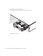

5-8
Sun Fire B1600 System Chassis Hardware Installation Guide • August 2003
Note –
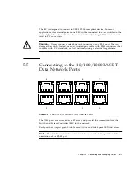
The ce0 interface of each blade is connected to the switch in SSC0 and the
ce1 interface of each blade is connected to the switch in SSC1. Both switches run in
parallel, but separately.
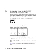
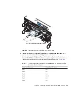
When LED A is illuminated constantly it indicates that a link is established, but no
packets are being transferred. When LED A is flashing it indicates that a link is
established, and packets are being transferred.
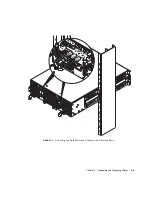
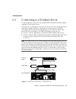
shows how to connect the data network cables to the system chassis.
If you intend to configure your system chassis with redundant data connections, see
Chapter 3 of the
Sun Fire B1600 Blade System Chassis Software Setup Guide
for details
of how to duplicate connections from the SSC to your network.
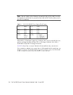
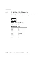
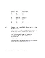
TABLE 5-1
10/100/1000BASE-T Data Network Port Pinouts
Pin 1
TRD0+
Pin 2
TRD0-
Pin 3
TRD1+
Pin 4
TRD2+
Pin 5
TRD2-
Pin 6
TRD1-
Pin 7
TRD3+
Pin 8
TRD3-
LED A
Link
Present/
Active
LED B
Link Speed:
On = 1000BASE-T
Off = 100BASE-T
Summary of Contents for Sun Fire B1600 Administration
Page 6: ...vi Sun Fire B1600 System Chassis Hardware Installation Guide August 2003 ...
Page 10: ...x Sun Fire B1600 System Chassis Hardware Installation Guide August 2003 ...
Page 14: ...xiv Sun Fire B1600 System Chassis Hardware Installation Guide August 2003 ...
Page 30: ...2 4 Sun Fire B1600 System Chassis Hardware Installation Guide August 2003 ...
Page 82: ...5 14 Sun Fire B1600 System Chassis Hardware Installation Guide August 2003 ...
Page 94: ...6 12 Sun Fire B1600 System Chassis Hardware Installation Guide August 2003 ...
Page 98: ...Index 4 Sun Fire B1600 System Chassis Hardware Installation Guide August 2003 ...