6-6
Sun Fire B1600 System Chassis Hardware Installation Guide • August 2003
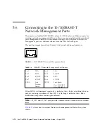
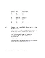
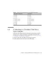
3. Plug the adapter into the DB-9 serial connector on the terminal you intend to use.
The DB-9 (9-pin) adapter must perform the pin interconnections listed in
.
6.5
Connecting to a Modem
For this connection, you can use the standard RJ-45 patch cable and the DB-25
adapter supplied with the server.
1. Connect one end of the serial cable to the serial port on the SSC.
2. Insert the other end of the serial cable into the DB-25 adapter that was supplied
with the system chassis (part number 530-2889).
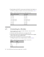
3. Plug the adapter into the DB-25 serial connector on the modem.
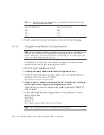
The settings you need to use for a modem connection are listed in
TABLE 6-4
Serial Port Pin Interconnections to a DB-9 (9-pin) Adapter
Serial Port (RJ-45 Connector) Pin
9-pin Connector
Pin 1 (RTS)
Pin 8 (CTS)
Pin 2 (DTR)
Pin 6 (DSR)
Pin 3 (TXD)
Pin 2 (RXD)
Pin 4 (Signal Ground)
Pin 5 (Signal Ground)
Pin 5 (Signal Ground)
Pin 5 (Signal Ground)
Pin 6 (RXD)
Pin 3 (TXD)
Pin 7 (DSR)
Pin 4 (DTR)
Pin 8 (CTS)
Pin 7 (RTS)
TABLE 6-5
Default Settings for Connecting a Modem to the Serial Port
Parameter
Setting
Rate
9600 baud
Parity
No
Stop bits
1
Data bits
8
Summary of Contents for Sun Fire B1600 Administration
Page 6: ...vi Sun Fire B1600 System Chassis Hardware Installation Guide August 2003 ...
Page 10: ...x Sun Fire B1600 System Chassis Hardware Installation Guide August 2003 ...
Page 14: ...xiv Sun Fire B1600 System Chassis Hardware Installation Guide August 2003 ...
Page 30: ...2 4 Sun Fire B1600 System Chassis Hardware Installation Guide August 2003 ...
Page 82: ...5 14 Sun Fire B1600 System Chassis Hardware Installation Guide August 2003 ...
Page 94: ...6 12 Sun Fire B1600 System Chassis Hardware Installation Guide August 2003 ...
Page 98: ...Index 4 Sun Fire B1600 System Chassis Hardware Installation Guide August 2003 ...

