Chapter 3
Understanding the Status Indicators
41
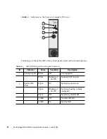
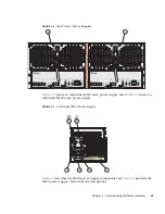
FIGURE 3-8
Individual J4400 Power Supply
TABLE 3-7
describes the J4400 power supply components and
TABLE 3-8
provides the
J4400 power supply status indicator descriptions.
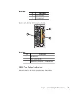
TABLE 3-7
J4400 Array Power Supply Components
ID
Component
Description
1
Cooling fan status indicator
See
TABLE 3-8
.
2
AC power status indicator
See
TABLE 3-8
.
3
DC power status indicator
See
TABLE 3-8
.
4
Power supply status indicator
See
TABLE 3-8
.
5
Power on/off switch
Turns power to the array on or off.
6
Power cord tie wrap
Holds the power cord in place.
7
Universal power input
connector
Provides power to the array.
8
Right ejection arm and captive
screw latch
Secures the power supply to the
chassis.
2
1
3
6
5
7
4
8
Summary of Contents for Sun Storage J4200
Page 10: ...x Sun Storage J4200 J4400 Array System Overview June 2009 ...
Page 16: ...xvi Sun Storage J4200 J4400 Array System Overview June 2009 ...
Page 46: ...30 Sun Storage J4200 J4400 Array System Overview June 2009 ...
Page 95: ...Chapter 5 SAS Multipathing 79 ...
Page 96: ...80 Sun Storage J4200 J4400 Array System Overview June 2009 ...
Page 97: ...Chapter 5 SAS Multipathing 81 ...
Page 98: ...82 Sun Storage J4200 J4400 Array System Overview June 2009 ...
Page 104: ...88 Sun Storage J4200 J4400 Array System Overview June 2009 ...
Page 110: ...94 Sun Storage J4200 J4400 Array System Overview June 2009 ...


