background image

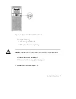
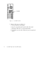
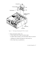
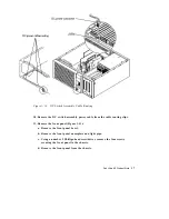
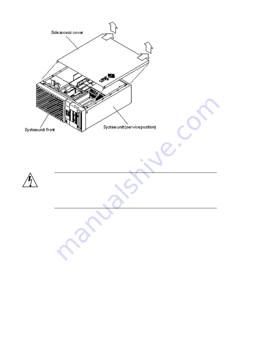
Figure 1–3

Removing the Side Access Cover

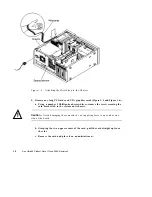
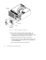
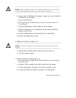
4. Attach the wrist strap (Figure 1–4):

Caution -

Wear an antistatic wrist strap and use an ESD-protected mat when

handling components. When servicing or removing system unit components, attach
an ESD strap to your wrist, then to a metal area on the chassis, and then disconnect
the power cord from the system unit and the wall receptacle. Following this caution
equalizes all electrical potentials with the system unit.

a. Unwrap the first two folds of the wrist strap; wrap the adhesive side firmly

against the wrist.

b. Peel the liner from the copper foil at the opposite end of the wrist strap.

c. Attach the copper end of the wrist strap to the chassis.

d. Disconnect the AC power cord.

Sun Ultra 60 Product Note

9

Summary of Contents for Sun Ultra 60

Page 1: ...Sun Ultra 60 Product Note 901 San Antonio Road Palo Alto CA 94303 4900 USA 650 960 1300 Fax 650 969 9131 Part Number 806 1056 11 June 2000 Revision A...

Page 2: ...THE EXTENT THAT SUCH DISCLAIMERS ARE HELD TO BE LEGALLY INVALID Copyright 2000 Sun Microsystems Inc 901 San Antonio Road Palo Alto Californie 94303 4900 U S A Tous droits r serv s Ce produit ou docum...

Page 3: ...ntents 1 Sun Ultra 60 Product Note 5 Special Considerations for Systems With 450 MHz CPU Modules 5 Energy Star Software Support 6 Removing the DC Switch Assembly 6 Replacing the DC Switch Assembly 19...

Page 4: ...4 Sun Ultra 60 Product Note June 2000 Revision A...

Page 5: ...ch Assembly on page 19 Special Considerations for Systems With 450 MHz CPU Modules If you plan on installing either the SolarisTM 2 5 1 or Solaris 2 6 operating environment you must install it using t...

Page 6: ...cted mat Store ESD sensitive components in antistatic bags before placing them on any surface Caution The DC switch assembly removal procedure is a complex procedure It is recommended that a qualified...

Page 7: ...panel LED is off ii The system fans are not spinning Caution Disconnect the AC power cord prior to servicing system components a Turn off the power to the monitor b Disconnect cables to any periphera...

Page 8: ...system in the service position b Grasp the side panel and pull it toward the back of the system c Disengage the side access cover from the chassis hooks d Grasping the access cover sides lift the sid...

Page 9: ...area on the chassis and then disconnect the power cord from the system unit and the wall receptacle Following this caution equalizes all electrical potentials with the system unit a Unwrap the first...

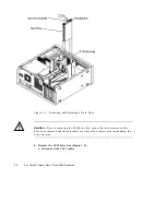
Page 10: ...ewdriver remove the screw securing the card bracket tab to the system unit chassis Caution Avoid damaging the connector by not applying force to one end or one side of the board b Grasping the two upp...

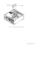
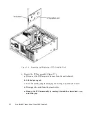
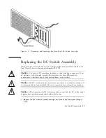
Page 11: ...Figure 1 5 Removing and Replacing a PCI Card Sun Ultra 60 Product Note 11...

Page 12: ...fan power harness from the motherboard b Lift the locking tab c Press the locking snap to disengage the locking snap from the chassis d Disengage the studs from the chassis slots e Remove the PCI fan...

Page 13: ...gure 1 8 a Push the handle latch to release the hard drive handle b Extend the hard drive handle to release the hard drive from the system unit c Holding the drive handle lift the hard drive from the...

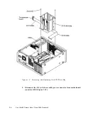
Page 14: ...g the SCSI drive bay ensure that all necessary cables have been removed and that all cables are clear of the chassis area surrounding the drive bay area 8 Remove the SCSI drive bay Figure 1 9 a Discon...

Page 15: ...eral power cable c Remove the peripheral power cable from the cable routing clips d Remove the diskette drive cable from the plastic spring clips installed adjacent to the drive bay e Feed the periphe...

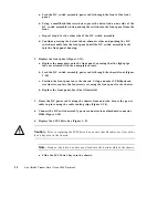
Page 16: ...Figure 1 9 Removing and Replacing the SCSI Drive Bay 9 Disconnect the DC switch assembly power connector from motherboard connector J3504 Figure 1 10 16 Sun Ultra 60 Product Note June 2000 Revision A...

Page 17: ...ting clips 11 Remove the front panel Figure 1 11 a Remove the front panel bezel b Remove the front panel nameplate and light pipe c Using a number 2 Phillips head screwdriver remove the four screws se...

Page 18: ...e side of the DC switch assembly while pushing the switch toward the front of the front panel b Repeat Step a for the other side of the DC switch assembly c Continue pressing the detent tab on alterna...

Page 19: ...strap and use an ESD protected mat Store ESD sensitive components in antistatic bags before placing them on any surface Caution The DC switch assembly replacement procedure is a complex procedure It...

Page 20: ...Feed the DC switch assembly power cable through the chassis front Figure 1 10 c Position the front panel onto the chassis Using a number 2 Phillips head screwdriver replace the four screws securing th...

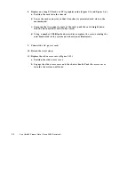
Page 21: ...ent to the drive bay g Route the peripheral power cable through the cable routing clips h Connect the peripheral power cable 6 Replace the hard drive s Figure 1 8 Caution Ensure that the hard drive is...

Page 22: ...down into the slot until the card is fully seated d Using a number 2 Phillips head screwdriver replace the screw securing the card bracket tab to the system unit chassis not illustrated 9 Connect the...

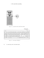
Page 23: ...cables to any peripheral equipment 15 Turn on the power to the monitor 16 Power on the system unit a Turn on power to all connected peripherals b Set the front panel power switch to the On position Fi...

Page 24: ...ii The system fans are spinning Figure 1 14 System Unit Power On Front Panel Figure 1 15 Sun Type 5 Keyboard 24 Sun Ultra 60 Product Note June 2000 Revision A...

Reviews: