Major Subassemblies
8-25
8
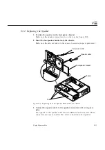
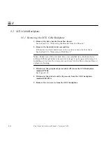
8.7 Speaker/LED Cable
8.7.1 Removing the Speaker/LED Cable
Note –
If the system does not contain a CD-ROM or a tape drive, go to Step 5.
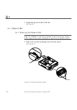
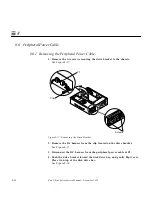
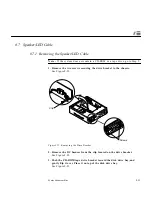
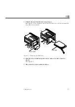
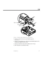
1. Remove the two screws securing the drive bracket to the chassis.
See Figure 8-22.
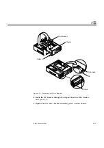
Figure 8-22 Removing the Drive Bracket
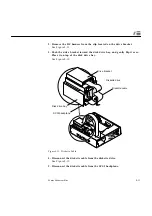
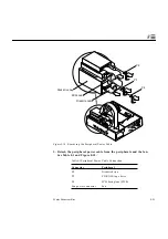
2. Remove the DC harness from the clip located on the drive bracket.
See Figure 8-22.
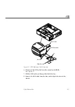
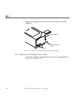
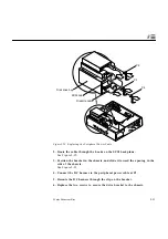
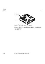
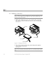
3. Push the CD-ROM/tape drive bracket toward the disk drive bay, and
gently flip it over. Place it on top of the disk drive bay.
See Figure 8-23.
Screws
Clip
Summary of Contents for Ultra 1 140
Page 6: ......
Page 8: ...Sun Ultra 1 Series Service Manual November 1995...
Page 12: ...x Sun Ultra 1 Series Service Manual November 1995 Glossary Glossary 1 Index Index 1...
Page 23: ...Part1 SystemInformation Product Description page 1 1...
Page 24: ......
Page 28: ...1 4 Sun Ultra 1 Series Service Manual November 1995 1...
Page 30: ......
Page 46: ...3 14 Sun Ultra 1 Series Service Manual November 1995 3...
Page 62: ...4 16 Sun Ultra 1 Series Service Manual November 1995 4...
Page 63: ...Part3 PreparingforService Safety and Tool Requirements page 5 1 Power On and Off page 6 1...
Page 64: ......
Page 68: ...5 4 Electron Service Manual November 1995 5...
Page 72: ......
Page 108: ...8 32 Sun Ultra 1 Series Service Manual November 1995 8...
Page 121: ...Part5 SystemBoard System Board and Component Replacement page 10 1...
Page 122: ......
Page 147: ...Part6 IllustratedPartsBreakdown Replacement Parts page 11 1...
Page 148: ......
Page 152: ......
Page 166: ...C 4 Sun Ultra 1 Series Service Manual November 1995 C...
Page 170: ...Glossary 4 Sun Ultra 1 Series Service Manual November 1995...
Page 174: ...Index 4 Sun Ultra 1 Series Service Manual November 1995...

