System Board and Component Replacement
10-9
10
The jumpers can be set as either RS-423 or RS-232 mode. The jumpers are
preset in RS-423 mode, the default standard for North American users.
RS-232 modes are required for digital telecommunication in nations of the
European Community.
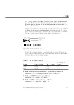
Jumpers are identified on the system board with silkscreened part numbers.
For example, the serial port jumpers are marked J2104 and J2105. Jumper
pins are located immediately adjacent to the part number. Pin 1 is marked
with an asterisk in any of the positions shown. See Figure 10-8.
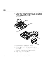
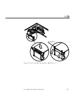
Figure 10-8 Identifying Jumper Pins
Be sure the serial port jumpers are set correctly. Use a pair of long-nose
pliers to move both jumpers to the correct positions. Table 10-1 shows the
correct setting for the serial port jumpers.
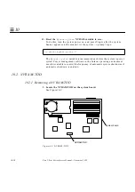
8. Replace the old NVRAM/TOD on the replacement system board.
See Section 10.2.2, “Replacing a NVRAM/TOD,” on page 11.
9. Replace all DSIMMs on the system board.
See Section 10.4, “DSIMM,” on page 18.
10. Replace all SBus card(s) on the system board.
See Section 10.3, “SBus Card,” on page 12.
Table 10-1 Serial Port Jumper Settings
Jumper
Pins 1 + 2 Select
Pins 2 + 3 Select
Default Shunt
on Pins
J2104
RS-232
RS-423
2 + 3
J2105
RS-232
RS-423
2 + 3
Pins
Part number
J 2 X X X
*
*
*
*
*
*
Summary of Contents for Ultra 1 140
Page 6: ......
Page 8: ...Sun Ultra 1 Series Service Manual November 1995...
Page 12: ...x Sun Ultra 1 Series Service Manual November 1995 Glossary Glossary 1 Index Index 1...
Page 23: ...Part1 SystemInformation Product Description page 1 1...
Page 24: ......
Page 28: ...1 4 Sun Ultra 1 Series Service Manual November 1995 1...
Page 30: ......
Page 46: ...3 14 Sun Ultra 1 Series Service Manual November 1995 3...
Page 62: ...4 16 Sun Ultra 1 Series Service Manual November 1995 4...
Page 63: ...Part3 PreparingforService Safety and Tool Requirements page 5 1 Power On and Off page 6 1...
Page 64: ......
Page 68: ...5 4 Electron Service Manual November 1995 5...
Page 72: ......
Page 108: ...8 32 Sun Ultra 1 Series Service Manual November 1995 8...
Page 121: ...Part5 SystemBoard System Board and Component Replacement page 10 1...
Page 122: ......
Page 147: ...Part6 IllustratedPartsBreakdown Replacement Parts page 11 1...
Page 148: ......
Page 152: ......
Page 166: ...C 4 Sun Ultra 1 Series Service Manual November 1995 C...
Page 170: ...Glossary 4 Sun Ultra 1 Series Service Manual November 1995...
Page 174: ...Index 4 Sun Ultra 1 Series Service Manual November 1995...


