System Board and Component Replacement
10-19
10
Note –
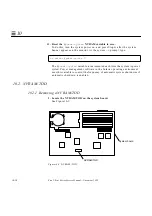
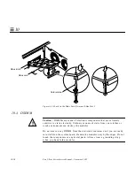
Each DSIMM removed from the system should be replaced with
another DSIMM. The replacement DSIMM should have the same capacity as
the defective one. It should also be inserted into the same socket as the
defective one.
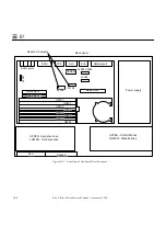
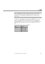
The Sun Ultra 1 Series system must have a pair of DSIMMs in bank 0 to be able
to boot. Up to eight DSIMMs can be installed in the system. They can be
located in the sockets described on Table 10-2. However, each bank must
contain two DSIMMs of equal density (for example: two 16MB DSIMMs, two
64MB DSIMMs) to function properly. Do not mix DSIMM densities in any
bank.
Table 10-2 Bank and Socket Locations for DSIMMs
Bank
Socket
0 (Required)
U0701 + U0601
1
U0702 + U0602
2
U0703 + U0603
3
U0704 + U0604
Summary of Contents for Ultra 1 140
Page 6: ......
Page 8: ...Sun Ultra 1 Series Service Manual November 1995...
Page 12: ...x Sun Ultra 1 Series Service Manual November 1995 Glossary Glossary 1 Index Index 1...
Page 23: ...Part1 SystemInformation Product Description page 1 1...
Page 24: ......
Page 28: ...1 4 Sun Ultra 1 Series Service Manual November 1995 1...
Page 30: ......
Page 46: ...3 14 Sun Ultra 1 Series Service Manual November 1995 3...
Page 62: ...4 16 Sun Ultra 1 Series Service Manual November 1995 4...
Page 63: ...Part3 PreparingforService Safety and Tool Requirements page 5 1 Power On and Off page 6 1...
Page 64: ......
Page 68: ...5 4 Electron Service Manual November 1995 5...
Page 72: ......
Page 108: ...8 32 Sun Ultra 1 Series Service Manual November 1995 8...
Page 121: ...Part5 SystemBoard System Board and Component Replacement page 10 1...
Page 122: ......
Page 147: ...Part6 IllustratedPartsBreakdown Replacement Parts page 11 1...
Page 148: ......
Page 152: ......
Page 166: ...C 4 Sun Ultra 1 Series Service Manual November 1995 C...
Page 170: ...Glossary 4 Sun Ultra 1 Series Service Manual November 1995...
Page 174: ...Index 4 Sun Ultra 1 Series Service Manual November 1995...


