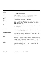
Signal Descriptions
B-3
B
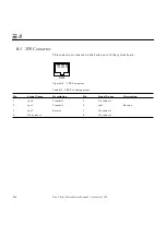
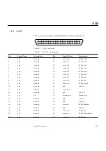
B.2 AUI (Attachment Unit Interface) Connector
This connector is located on the back panel of the system board.
Figure B-3
AUI Connector
Table 11-2 AUI Connector Pinouts
Pin
Function
1
Gnd
2
3
4
Gnd
5
6
Gnd
7
NC
8
Gnd
9
AUI_CI-
10
AUI_DO-
11
Gnd
12
AUI_DI-
13
+12 VDC
14
Gnd
15
NC
Summary of Contents for Ultra 1 140
Page 6: ......
Page 8: ...Sun Ultra 1 Series Service Manual November 1995...
Page 12: ...x Sun Ultra 1 Series Service Manual November 1995 Glossary Glossary 1 Index Index 1...
Page 23: ...Part1 SystemInformation Product Description page 1 1...
Page 24: ......
Page 28: ...1 4 Sun Ultra 1 Series Service Manual November 1995 1...
Page 30: ......
Page 46: ...3 14 Sun Ultra 1 Series Service Manual November 1995 3...
Page 62: ...4 16 Sun Ultra 1 Series Service Manual November 1995 4...
Page 63: ...Part3 PreparingforService Safety and Tool Requirements page 5 1 Power On and Off page 6 1...
Page 64: ......
Page 68: ...5 4 Electron Service Manual November 1995 5...
Page 72: ......
Page 108: ...8 32 Sun Ultra 1 Series Service Manual November 1995 8...
Page 121: ...Part5 SystemBoard System Board and Component Replacement page 10 1...
Page 122: ......
Page 147: ...Part6 IllustratedPartsBreakdown Replacement Parts page 11 1...
Page 148: ......
Page 152: ......
Page 166: ...C 4 Sun Ultra 1 Series Service Manual November 1995 C...
Page 170: ...Glossary 4 Sun Ultra 1 Series Service Manual November 1995...
Page 174: ...Index 4 Sun Ultra 1 Series Service Manual November 1995...

