Chapter 10
System Board and Component Replacement
10-7
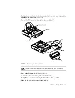
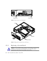
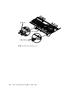
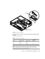
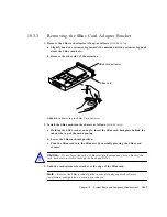
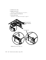
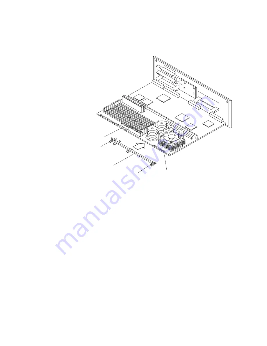
FIGURE 10-6
Installing the Card Guide
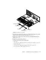
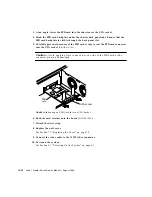
3. Slide the system board into the chassis rear. Verify that both sides of the system
board fit into the chassis plastic board guide slots (
FIGURE 10-7
).
4. Tighten the two captive screws that secure the system board back panel to the
chassis (
FIGURE 10-2
).
5. Populate the system board as follows:
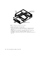
a. Connect the following to the system board:
■
SCSI cable
See Section 8.5.2 “Replacing the SCSI Cable/Backplane Assembly” on page 8-21.
■
Speaker/LED cable
See Section 8.7.2 “Replacing the Speaker/LED Cable” on page 8-34.
■
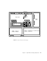
DC power cables at J2601 and J2603 (
FIGURE 10-8
).
Card guide
Vertical tab
Front edge slot
Registration pin
Front edge slot
Summary of Contents for Ultra 1 Series
Page 8: ...viii Ultra 1 Creator Series Service Manual August 1996...
Page 21: ...Preface xxi Email smcc docs sun com Fax SMCC Document Feedback 1 415 786 6443...
Page 22: ...xxii Ultra 1 Creator Series Service Manual August 1996...
Page 34: ...2 4 Ultra 1 Creator Series Service Manual August 1996...
Page 70: ...6 4 Ultra 1 Creator Series Service Manual August 1996...
Page 110: ...8 36 Ultra 1 Creator Series Service Manual August 1996...
Page 126: ...9 16 Ultra 1 Creator Series Service Manual August 1996...
Page 158: ...10 32 Ultra 1 Creator Series Service Manual August 1996...
Page 164: ...A 4 Ultra 1 Creator Series Service Manual August 1996...
Page 186: ...B 22 Ultra 1 Creator Series Service Manual August 1996...
Page 208: ...C 22 Ultra 1 Creator Series Service Manual August 1996...
Page 212: ...Glossary 4 Ultra 1 Creator Series Service Manual August 1996...

