Chapter 10
System Board and Component Replacement
10-13
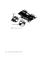
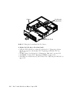
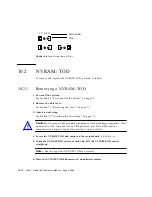
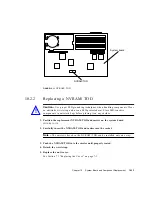
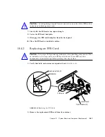
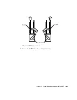
FIGURE 10-11
NVRAM/TOD
10.2.2
Replacing a NVRAM/TOD
Caution –
Use proper ESD grounding techniques when handling components. Wear
an antistatic wrist strap and use an ESD-protected mat. Store ESD-sensitive
components in antistatic bags before placing it on any surface.
1. Position the replacement NVRAM/TOD and carrier on the system board
(
FIGURE 10-11
).
2. Carefully insert the NVRAM/TOD and carrier into the socket.
Note –
The carrier is keyed so the NVRAM/TOD can be installed only one way.
3. Push the NVRAM/TOD into the carrier until properly seated.
4. Detach the wrist strap.
5. Replace the unit cover.
See Section 7.3 “Replacing the Cover” on page 7-3.
NVRAM/TOD
System board
!
Summary of Contents for Ultra 1 Series
Page 8: ...viii Ultra 1 Creator Series Service Manual August 1996...
Page 21: ...Preface xxi Email smcc docs sun com Fax SMCC Document Feedback 1 415 786 6443...
Page 22: ...xxii Ultra 1 Creator Series Service Manual August 1996...
Page 34: ...2 4 Ultra 1 Creator Series Service Manual August 1996...
Page 70: ...6 4 Ultra 1 Creator Series Service Manual August 1996...
Page 110: ...8 36 Ultra 1 Creator Series Service Manual August 1996...
Page 126: ...9 16 Ultra 1 Creator Series Service Manual August 1996...
Page 158: ...10 32 Ultra 1 Creator Series Service Manual August 1996...
Page 164: ...A 4 Ultra 1 Creator Series Service Manual August 1996...
Page 186: ...B 22 Ultra 1 Creator Series Service Manual August 1996...
Page 208: ...C 22 Ultra 1 Creator Series Service Manual August 1996...
Page 212: ...Glossary 4 Ultra 1 Creator Series Service Manual August 1996...


