background image

Preface

xxi

Email:smcc-docs@sun.com

Fax:

SMCC Document Feedback

1-415-786-6443

Summary of Contents for Ultra 1 Series

Page 1: ...this document to docfeedback sun com Ultra 1 Creator Series Service Manual Part No 802 4148 10 Revision A August 1996 Sun Microsystems Inc 901 San Antonio Road Palo Alto CA 94303 4900 USA 650 960 130...

Page 2: ...FOR A PARTICULAR PURPOSE OR NON INFRINGEMENT Copyright 1997 Sun Microsystems Inc 901 San Antonio Road Palo Alto Californie 94303 4900 U S A Tous droits r serv s Ce produit ou document est prot g par u...

Page 3: ...Series Desktop 1 4 1 3 1 System Unit Features 1 4 1 3 2 System Unit Components 1 5 2 SunVTS Overview 2 1 2 1 SunVTS Overview 2 1 2 1 1 SunVTS Kernel 2 2 2 1 2 SunVTS User Interface 2 2 2 1 3 SunVTS Te...

Page 4: ...ng Procedures 4 1 4 1 Power On Failure 4 1 4 2 Video Output Failure 4 2 4 3 Disk or CD ROM Drive Failure 4 2 4 4 Power Supply Test 4 4 4 5 DSIMM Failure 4 7 4 6 OpenBoot PROM On Board Diagnostics 4 8...

Page 5: ...8 3 8 2 Disk Drive Fan 8 5 8 2 1 Removing the Disk Drive Fan Assembly 8 6 8 2 2 Replacing the Disk Drive Fan 8 7 8 3 Speaker 8 9 8 3 1 Removing the Speaker 8 9 8 3 2 Replacing the Speaker 8 12 8 4 Di...

Page 6: ...D ROM Drive or 4 mm 8 mm Tape Drive 9 10 9 3 2 Replacing a CD ROM Drive or 4 mm 8 mm Tape Drive 9 11 9 4 Diskette Drive 9 12 9 4 1 Removing a Diskette Drive 9 12 9 4 2 Replacing a Diskette Drive 9 14...

Page 7: ...Removing a DSIMM 10 24 10 5 2 Replacing a DSIMM 10 26 10 6 System Board Fan 10 28 10 6 1 Removing the System Board Fan 10 28 10 6 2 Replacing the Board Fan 10 30 11 Replacement Parts 11 1 A Product Sp...

Page 8: ...viii Ultra 1 Creator Series Service Manual August 1996...

Page 9: ...r J2601 4 5 FIGURE 4 2 Power Supply Connector J2603 4 6 FIGURE 6 1 Rear View of the System 6 1 FIGURE 6 2 Sun Type 5 Keyboard 6 2 FIGURE 7 1 Location of Lock Block 7 1 FIGURE 7 2 Removing the Cover 7...

Page 10: ...Drive Bracket 8 24 FIGURE 8 18 Removing the Peripheral Power Cable Connection 8 25 FIGURE 8 19 Backplane Assembly Peripheral Power Cable Routing 8 26 FIGURE 8 20 Replacing the Peripheral Power Cable C...

Page 11: ...he Card Guide 10 7 FIGURE 10 7 Sliding the System Board Into The Chassis 10 8 FIGURE 10 8 DC Power Connection 10 9 FIGURE 10 9 Location of the Serial Port Jumpers 10 11 FIGURE 10 10 Identifying Jumper...

Page 12: ...Configuration B 5 FIGURE B 4 Fast Wide SCSI Connector Configuration B 6 FIGURE B 5 Audio Connector Configuration B 10 FIGURE B 6 Parallel Port Connector Pin Configuration B 11 FIGURE B 7 MII Connecto...

Page 13: ...cal Memory Address 4 7 TABLE 4 5 Selected OBP On Board Diagnostic Tests 4 13 TABLE 8 1 Peripheral Power Cable Connections 8 25 TABLE 10 1 Serial Port Jumper Settings 10 9 TABLE 10 2 DSIMM Bank and Soc...

Page 14: ...tor Pin Assignments B 13 TABLE B 8 UPA Connector Pin Assignments B 15 TABLE B 9 Graphics Card 13W3 Video Connector Pin Assignments B 21 TABLE C 1 Supported Disk Drives C 6 TABLE C 2 Audio Port Functio...

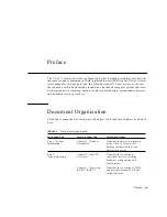
Page 15: ...ce providers Document Organization This book is comprised of seven parts Each part is divided into chapters as listed in here TABLE P 1 Document Organization Part Number Title Chapter Number Title Con...

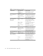
Page 16: ...ace major subassemblies Chapter 9 Storage Devices Provides step by step procedures to remove and replace storage devices Part 5 System Board Chapter 10 System Board and Component Replacement Provides...

Page 17: ...n ESD protected mat Store ESD sensitive components in antistatic bags before placing it on any surface Individuals servicing this equipment must observe all safety precautions and ensure compliance wi...

Page 18: ...les machine_name You have mail AaBbCc123 What you type contrasted with on screen computer output machine_name suPassword AaBbCc123 Command line placeholder replace with a real name or value To delete...

Page 19: ...75 Specification 4 mm Tape Drive Specifications 802 5324 Diagnostic SunVTS 1 0 User s Guide 801 7271 Diagnostic SunVTS 1 0 Test Reference Manual 802 1448 Diagnostic SunVTS 1 0 Quick Reference Card 802...

Page 20: ...ntation and welcome your comments and suggestions You can also email or fax your comments to us Please include the part number of your document in the subject line of your email or fax message TABLE P...

Page 21: ...Preface xxi Email smcc docs sun com Fax SMCC Document Feedback 1 415 786 6443...

Page 22: ...xxii Ultra 1 Creator Series Service Manual August 1996...
Page 23: ...elerated graphics 1 1 Ultra 1 Series Overview Major components comprising the Ultra 1 Creator series desktop workstation and the Ultra Enterprise 1 server include I O devices Monitor included with des...

Page 24: ...ies Desktop System FIGURE 1 2 Ultra Enterprise 1 Server The following sections provide a brief description of the Ultra 1 Creator series desktop workstation I O devices Also included is a detailed ove...

Page 25: ...Device Description 17 inch 43 cm color monitor 1152 x 900 resolution 76 or 66 Hz refresh rate 100 dots per inch DPI 1280 x 1024 resolution 76 or 66 Hz refresh rate 110 DPI 960 x 680 resolution 112 Hz...

Page 26: ...atures SPARCTM V9 64 bit UltraSPARCTM processor 167 Megahertz MHz processor 200 MHz processor SolarisTM 2 5 1 operating system SolarisTM 2 5 Hardware 1 96 High performance UltraSPARC Port Architecture...

Page 27: ...support 1 3 2 System Unit Components System unit components are listed in TABLE 1 2 FIGURE 1 3 illustrates the system unit interior FIGURE 1 4 illustrates the system unit rear panel Note Part numbers...

Page 28: ...d single buffer 67 MHz Drive 540 2729 1 05 Gbyte disk drive Drive 540 2730 2 1 Gbyte disk drive Drive 370 2102 CD ROM drive 1 6 inch Drive 370 2151 Diskette drive Power supply 300 1308 180 W power sup...

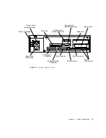
Page 29: ...SCSI connector TPE connector MII connector Serial port A Serial port B Audio Power on standby Power outlet Female socket UPA slot RS 423 RS 232 RS 423 RS 232 SBus slot 1 SBus slot 0 Power inlet Male...

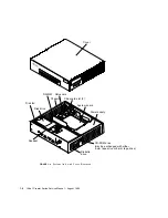
Page 30: ...gust 1996 FIGURE 1 4 System Unit with Cover Removed Cover Chassis SBus card SBus card slot 2 System board Power supply DSIMM Disk drive Disk fan Speaker Diskette drive CD ROM drive may be exchanged wi...

Page 31: ...ge 2 SunVTS User Interface on page 2 SunVTS Teletype on page 3 2 1 SunVTS Overview The SunVTS software executes multiple diagnostic hardware tests from a single user interface and is used to verify co...

Page 32: ...activated vtsk probes the hardware configuration of the system tested and responds to vtsui vtsk coordinates execution of individual tests and manages the messages sent by these tests 2 1 2 SunVTS Use...

Page 33: ...ew 2 3 2 1 3 SunVTS Teletype The SunVTS teletype vtstty diagnostic tool controls the vtsk from either a command shell or a terminal attached to a serial port Most options available in vtstty have equi...

Page 34: ...2 4 Ultra 1 Creator Series Service Manual August 1996...

Page 35: ...Pre POST Preparation on page 2 Initilizing POST on page 4 Max and Min Levels of POST on page 5 POST Progress and Error Reporting on page 10 Bypassing POST on page 11 Additional Keyboard Control Comma...

Page 36: ...tion or server to be tested the keyboard LEDs are used to determine error conditions see Section 3 9 System and Keyboard LEDs on page 3 12 3 2 1 Setting Up a Tip Connection A tip connection permits a...

Page 37: ...w on the Sun Workstation enter tip hardwire The system replies Note The shell window is now a tip window directed to the serial port of the Sun Workstation or server being tested When power is applied...

Page 38: ...ilizing POST POST may be initilized by two ways by setting the diag switch NVRAM variable to true and then power cycling the system or by simultaneously pressing the keyboard Stop and D keys while pow...

Page 39: ...initiates the selected level of POST based upon the setting of diag level a NVRAM variable The default setting for diag level is max An example of a max level POST output on serial port A is provided...

Page 40: ...etenv diag level max CODE EXAMPLE 3 1 Diag level NVRAM Variable Set to Max ok Hardware Power ON Button Power ON Button Power ON Sun Ultra X UPA SBus X X X X FCS Test PROM Version X created XXXX XX XX...

Page 41: ...M Test 0 Data Cache RAM Test 0 Data Cache Tags Test 0 MMU Enable Test 0 DMMU Registers Access Test 0 DMMU TLB DATA RAM Access Test 0 DMMU TLB TAGS Access Test 0 IMMU Registers Access Test 0 IMMU TLB D...

Page 42: ...Config Registers Test 0 SysIO RAM Initialization 0 SysIO Functional Test 0 Mapping Selftest Enabling MMUs 0 Clear Interrupt Map and State Registers 0 SysIO Interrupts Test 0 SysIO Timers Counters Test...

Page 43: ...Internal Loopbacks Test 0 Ethernet Transceiver Internal Loopbacks Test 0 CPU Functional Test 0 Mapping Selftest Enabling MMUs 0 SPARC Atomic Instructions Test 0 CPU Dispatch Control Register Test 0 C...

Page 44: ...ndicator stops flashing and an error code is displayed using the Caps Lock Compose Scroll Lock and Num Lock key indicators The error code indicates a particular system hardware failure CODE EXAMPLE 3...

Page 45: ...or code by comparing the keyboard error code pattern to the corresponding error code meaning listed in TABLE 3 2 on page 3 13 Note The system does not automatically boot if a POST error occurs it halt...

Page 46: ...and N keys until the system banner appears on the monitor 3 9 System and Keyboard LEDs The power LED located at the chassis front remains lighted when the system is operating normally FIGURE 3 2 shows...

Page 47: ...2 POST in progress Off Off Off Off 0000 2 POST successful completion Off Off Off On 0001 2 DSIMM in slot U 0601 failure Off Off On Off 0010 2 DSIMM in slot U 0701 failure Off Off On On 0011 2 DSIMM in...

Page 48: ...m and Keyboard LEDs on page 3 12 Note The most probable cause of this type of failure is the system board However optional system components could also cause POST to fail 5 Before replacing the system...

Page 49: ...hen the keyboard power switch is pressed ACTION Check the AC power cord Ensure that the AC power cord is properly connected to the system unit and to the wall receptacle Verify that the wall receptacl...

Page 50: ...nit still fails to initialize refer to Section 3 9 System and Keyboard LEDs on page 3 12 4 2 Video Output Failure The following provides an example of a video output failure symptom and suggested acti...

Page 51: ...ACTION Test the drive response to the probe scsi command as follows 1 At the system ok prompt a Enter reset all b Enter probe scsi 2 If the disk drive responds correctly to probe scsi the message ide...

Page 52: ...provides instructions to test the power supply Note FIGURE 4 1 and TABLE 4 2 identify power supply connector J2601 FIGURE 4 2 and TABLE 4 3 identify power supply connector J2603 Use a digital voltage...

Page 53: ...tor J2601 TABLE 4 2 Connector 2601 Pin Description Pin Description Pin Description 1 12V 9 Thermal sensor 2 Gnd 10 12V 3 Power on 11 Power off 4 Not used 12 Undefined 5 Not used 13 Undefined 6 3V sens...

Page 54: ...1996 FIGURE 4 2 Power Supply Connector J2603 TABLE 4 3 Connector 2603 Pin Description Pin Description Pin Description 1 5V 10 Gnd 2 5V 11 Gnd 3 5V 12 Gnd 4 3 3V 13 Gnd 5 3 3V 14 Gnd 6 3 3V 15 Gnd 7 3...

Page 55: ...64 Mbyte or two 128 Mbyte DSIMMs Unused addresses are mapped out by the memory management hardware Regardless of the installed DSIMM capacity the physical memory starting address is as listed in TABL...

Page 56: ...unter During normal operation the seconds counter repeatedly increments from 0 to 59 until interrupted by pressing any key on the Sun type 5 keyboard CODE EXAMPLE 4 1 identifies the watch clock output...

Page 57: ...or and the cyclic redundancy check CRC error are indicated with an X and an associated error description CODE EXAMPLE 4 2 identifies the watch net output message CODE EXAMPLE 4 3 identifies the watch...

Page 58: ...irst identifier listed in the display is the SCSI host adapter address in the system device tree followed by the SCSI device identification data CODE EXAMPLE 4 3 watch net all Output Message ok watch...

Page 59: ...Enter n Enter reset all Verify display blanks for approximately 5 seconds and returns to the ok prompt ok probe scsi This command may hang the system if a Stop A or halt command has been executed Ple...

Page 60: ...lease type reset all to reset the system before executing this command Do you wish to continue y n Enter n Enter reset all Verify display blanks for approximately 5 seconds and returns to the ok promp...

Page 61: ...Tests system video graphics hardware and monitor Diag switch NVRAM parameter must be true for the test to execute test floppy Tests floppy drive response to commands A formatted diskette must be inse...

Page 62: ...prompt a A series of patterns are displayed b FFB Frame Buffer functional test passed appears 3 Enter test SUNW ffb at the ok prompt a A series of patterns are displayed b FFB Frame Buffer functional...

Page 63: ...following safety precautions when setting up the equipment Follow all cautions warnings and instructions marked on the equipment Ensure that the voltages and frequency rating of the power receptacle m...

Page 64: ...nal injury if touched 5 3 Safety Precautions The following safety precautions mean 5 3 1 Modification to Equipment Caution Do not make mechanical or electrical modifications to the equipment Sun Micro...

Page 65: ...The boards and hard disk drive contain electronic components that are extremely sensitive to static electricity Ordinary amounts of static electricity from clothes or work environment can destroy comp...

Page 66: ...d TOD NVRAM on an antistatic surface The following items can be used as an antistatic surface Bag used to wrap a Sun replacement part Shipping container used to package a Sun replacement part Inner si...

Page 67: ...e System To power on the system proceed as follows 1 Turn on power to all connected peripherals Note Peripheral power is activated prior to system power so the system can recognize the peripherals whe...

Page 68: ...system is going down 2 Back up system files and data 3 Halt the system 4 Set the power on standby switch to the stand by O position FIGURE 6 1 or press the Sun Type 5 keyboard power on key FIGURE 6 2...

Page 69: ...he power on standby switch is in stand by 0 and the AC power cord remains connected to a power receptacle AC voltage is present in the power supply primary 7 Turn off the power to the monitor 8 Discon...

Page 70: ...6 4 Ultra 1 Creator Series Service Manual August 1996...
Page 71: ...e Cover on page 1 Attaching the Wrist Strap on page 2 Replacing the Cover on page 3 7 1 Removing the Cover To remove the cover 1 Power off the system See Section 6 2 Powering Off the System on page 6...

Page 72: ...use an ESD protected mat when handling components When removing components other than the power supply leave the power cord connected to both the system server unit and the wall receptacle When removi...

Page 73: ...3 Replacing the Cover To replace the cover 1 Position the cover on the system FIGURE 7 4 2 Lower the rear of the cover until the cover channels align with the chassis flanges Press down on each side o...

Page 74: ...7 4 Ultra 1 Creator Series Service Manual August 1996 5 Power on the system FIGURE 7 4 Replacing the Cover Cover Flange Flange Channel 2 places Captive screw 2...

Page 75: ...23 Speaker LED Cable on page 29 8 1 Power Supply To remove and replace the power supply proceed as follows Caution When removing the power supply attach the copper end of the wrist strap to the system...

Page 76: ...7 2 Attaching the Wrist Strap on page 7 2 4 Disconnect the AC power cord from the system 5 Disconnect the power supply as follows FIGURE 8 1 a Disconnect the power supply connector from the system bo...

Page 77: ...handling components Wear an antistatic wrist strap and use an ESD protected mat Store ESD sensitive components in antistatic bags before placing it on any surface 1 Position the power supply into the...

Page 78: ...l 4 Connect the power supply as follows FIGURE 8 3 a Connect the DC connector to the peripheral power cable at P1 b Route and insert the DC harness through the clip on the drive bracket c Connect the...

Page 79: ...e system See Section 6 1 Powering On the System on page 6 1 FIGURE 8 3 Securing and Connecting the Power Supply 8 2 Disk Drive Fan To remove and replace the disk drive fan assembly proceed as follows...

Page 80: ...Use proper ESD grounding techniques when handling components Wear an antistatic wrist strap and use an ESD protected mat Store ESD sensitive components in antistatic bags before placing it on any sur...

Page 81: ...e Disk Drive Fan Caution Use proper ESD grounding techniques when handling components Wear an antistatic wrist strap and use an ESD protected mat Store ESD sensitive components in antistatic bags befo...

Page 82: ...ion 2 Insert the fan assembly into the fan speaker bracket in the chassis 3 Connect the fan connector to the fan power cable FIGURE 8 4 4 Detach the wrist strap 5 Replace the system unit cover See Sec...

Page 83: ...en handling components Wear an antistatic wrist strap and use an ESD protected mat Store ESD sensitive components in antistatic bags before placing it on any surface 3 Attach the wrist strap See Secti...

Page 84: ...8 10 Ultra 1 Creator Series Service Manual August 1996 FIGURE 8 7 Fan and Speaker Cable Connection Fan power cable Speaker Fan Speaker connector 2...

Page 85: ...ter 8 Major Subassemblies 8 11 FIGURE 8 8 Removing the Fan Speaker Bracket 5 Release the bottom portion of the speaker from the bracket and remove the speaker FIGURE 8 9 Chassis Fan speaker bracket Ta...

Page 86: ...ents Wear an antistatic wrist strap and use an ESD protected mat Store ESD sensitive components in antistatic bags before placing it on any surface 1 Replace the fan speaker bracket as follows FIGURE...

Page 87: ...n the top 2 Connect the speaker as follows FIGURE 8 7 a Use needle nose pliers to connect the speaker cable to the speaker Note Speaker cable connectors are keyed to ensure correct connection b Connec...

Page 88: ...ering Off the System on page 6 2 2 Remove the system unit cover See Section 7 1 Removing the Cover on page 7 1 Caution Use proper ESD grounding techniques when handling components Wear an antistatic w...

Page 89: ...bassemblies 8 15 5 Disconnect the diskette cable from the diskette drive 6 Disconnect the diskette cable from the SCSI backplane 7 Remove the diskette cable FIGURE 8 11 Removing the Drive Bracket Moun...

Page 90: ...ng components Wear an antistatic wrist strap and use an ESD protected mat Store ESD sensitive components in antistatic bags before placing it on any surface 1 Connect the diskette cable to the socket...

Page 91: ...toward the openings in the side of the chassis Note The hooks in the chassis base must lock into the holes in the bottom of the drive bracket c Route the DC harness through the clip on the side of th...

Page 92: ...es Service Manual August 1996 FIGURE 8 13 Replacing the Drive Bracket 8 5 SCSI Cable Backplane Assembly To remove and replace the SCSI cable backplane assembly proceed as follows Screw 2 Drive bracket...

Page 93: ...bracket from the chassis See Section 9 2 1 Removing the Chassis Bracket on page 9 5 Caution Each drive slot has a unique SCSI target address lower drive slot is target address 0 upper drive slot is ta...

Page 94: ...8 20 Ultra 1 Creator Series Service Manual August 1996 FIGURE 8 14 SCSI Backplane Assembly Cable Connection Diskette cable Backplane assembly SCSI cable P4 Screw 2...

Page 95: ...ll the SCSI cable out through the disk drive bay 10 Remove the SCSI cable from the cable clips in the base of the chassis 11 Remove the backplane assembly from the bracket 8 5 2 Replacing the SCSI Cab...

Page 96: ...plane assembly on the disk drive bay so the backplane assembly slots sit on the tabs FIGURE 8 16 4 Replace the two screws securing the backplane assembly to the bracket FIGURE 8 16 Replacing the SCSI...

Page 97: ...9 Replace the system unit cover See Section 7 3 Replacing the Cover on page 7 3 10 Power on the system See Section 6 1 Powering On the System on page 6 1 8 6 Peripheral Power Cable To remove and repl...

Page 98: ...DC harness from the peripheral power cable at P1 FIGURE 8 17 Removing the Drive Bracket 5 Position the drive bracket as follows 8 18 a Push the drive bracket toward the disk drive bay b Gently flip t...

Page 99: ...7 Remove the peripheral power cable FIGURE 8 18 Removing the Peripheral Power Cable Connection TABLE 8 1 Peripheral Power Cable Connections Connector Peripheral P2 Diskette drive Diskette drive bay S...

Page 100: ...ponents Wear an antistatic wrist strap and use an ESD protected mat Store ESD sensitive components in antistatic bags before placing it on any surface 1 Connect the peripheral power cable to each peri...

Page 101: ...on and secure the drive bracket as follows FIGURE 8 21 a Position the drive bracket in the chassis slide the drive bracket toward the opening in the chassis side b Connect the DC harness to the periph...

Page 102: ...tach the wrist strap 5 Replace the system unit cover See Section 7 3 Replacing the Cover on page 7 3 6 Power on the system See Section 6 1 Powering On the System on page 6 1 FIGURE 8 21 Replacing the...

Page 103: ...SD grounding techniques when handling components Wear an antistatic wrist strap and use an ESD protected mat Store ESD sensitive components in antistatic bags before placing it on any surface 3 Attach...

Page 104: ...8 22 Removing the Drive Bracket 5 Position the CD ROM tape drive bracket as follows FIGURE 8 23 a Push the CD ROM tape drive bracket toward the disk drive bay and gently flip it over b Place the CD RO...

Page 105: ...mblies 8 31 FIGURE 8 23 Placing the Bracket on Top of the Disk Drive 6 Slide the LED from the cavity and remove the speaker LED cable from the two cable clips FIGURE 8 24 Drive bracket CD ROM drive ta...

Page 106: ...speaker LED cable from the speaker FIGURE 8 25 8 Remove any SBus card s See Section 10 3 1 Removing an SBus Card on page 10 14 9 Disconnect the speaker LED cable from the system board at J2001 FIGURE...

Page 107: ...Chapter 8 Major Subassemblies 8 33 FIGURE 8 25 Speaker LED Cable Connection FIGURE 8 26 Speaker Connector on the System Board Speaker connector 2 Speaker Speaker LED cable System board J2001...

Page 108: ...eaker LED cable to the speaker FIGURE 8 25 Note The speaker LED cable connectors are keyed to ensure correct connection 4 Route the speaker LED cable through the cable clips and insert the LED into th...

Page 109: ...Chapter 8 Major Subassemblies 8 35 FIGURE 8 27 Replacing the Drive Bracket DC Harness Drive bracket Chassis Clip Hole 3 P1 Screw 2...

Page 110: ...8 36 Ultra 1 Creator Series Service Manual August 1996...

Page 111: ...1 Disk Drive To remove and replace a disk drive proceed as follows 9 1 1 Removing a Disk Drive 1 Power off the system See Section 6 2 Powering Off the System on page 6 2 2 Remove the system unit cover...

Page 112: ...door from the right side of the chassis FIGURE 9 1 5 Open the disk drive handle FIGURE 9 1 EMI Door 6 Fully extend the disk drive handle to disconnect the disk drive from the system FIGURE 9 2 FIGURE...

Page 113: ...of a disk drive into an incorrect drive slot can cause file system or system boot problems Caution Use proper ESD grounding techniques when handling components Wear an antistatic wrist strap and use...

Page 114: ...over will not fit correctly a Position the EMI door on the chassis the two tabs should be hooked into the two slots b Push the EMI door in until it is flush with the chassis 4 Detach the wrist strap 5...

Page 115: ...8 mm tape drive or the diskette drive The chassis bracket is not a field replaceable unit FRU To remove and replace the chassis bracket proceed as follows 9 2 1 Removing the Chassis Bracket 1 Remove t...

Page 116: ...bay and gently flip the chassis bracket over and place it on top of the disk drive bay b Disconnect the SCSI cable from the CD ROM tape drive c Disconnect the peripheral power cable from the CD ROM d...

Page 117: ...acing the Chassis Bracket Caution Use proper ESD grounding techniques when handling components Wear an antistatic wrist strap and use an ESD protected mat Store ESD sensitive components in antistatic...

Page 118: ...cket if present FIGURE 9 7 a The diskette cable to the diskette drive b The peripheral power cable to the CD ROM drive or tape drive P3 and to the diskette drive P2 c The SCSI cable to the CD ROM driv...

Page 119: ...at P1 FIGURE 9 8 Positioning the Chassis Bracket Note Hooks at the chassis base must lock into the bottom holes of the drive bracket 4 Replace the DC harness as follows FIGURE 9 5 a Route the DC harn...

Page 120: ...trap and use an ESD protected mat Store ESD sensitive components in antistatic bags before placing it on any surface 3 Attach the wrist strap See Section 7 2 Attaching the Wrist Strap on page 7 2 4 Re...

Page 121: ...ar an antistatic wrist strap and use an ESD protected mat Store ESD sensitive components in antistatic bags before placing it on any surface 1 Position and align the CD ROM drive or 4 mm 8 mm tape dri...

Page 122: ...ection 6 1 Powering On the System on page 6 1 9 4 Diskette Drive To remove and replace the diskette drive proceed as follows 9 4 1 Removing a Diskette Drive 1 Power off the system See Section 6 2 Powe...

Page 123: ...ng a CD ROM Drive or 4 mm 8 mm Tape Drive on page 9 10 6 Remove the four screws securing the diskette drive to the chassis bracket FIGURE 9 10 7 Remove the diskette drive 8 Place the diskette drive on...

Page 124: ...efore placing it on any surface 1 Position the diskette drive in the chassis bracket FIGURE 9 11 FIGURE 9 11 Positioning the Diskette Drive 2 Replace the four screws 3 Replace the CD ROM drive or 4 mm...

Page 125: ...Chapter 9 Storage Devices 9 15 6 Replace the system unit cover See Section 7 3 Replacing the Cover on page 7 3 7 Power on the system See Section 6 1 Powering On the System on page 6 1...

Page 126: ...9 16 Ultra 1 Creator Series Service Manual August 1996...
Page 127: ...e 23 System Board Fan on page 28 10 1 System Board To remove and replace a system board proceed as follows Caution Use an antistatic mat when working with the system board An antistatic mat contains t...

Page 128: ...1 Removing the Cover on page 7 1 4 Attach a wrist strap See Section 7 2 Attaching the Wrist Strap on page 7 2 Caution Use proper ESD grounding techniques when handling components Wear an antistatic w...

Page 129: ...J2603 FIGURE 10 1 FIGURE 10 1 DC Power Disconnection 7 Loosen the two captive screws that secure the system board back panel to the chassis FIGURE 10 2 8 Grasp the system board and slide it out of th...

Page 130: ...em Board Out of the Chassis 10 1 2 Replacing a System Board Caution Use proper ESD grounding techniques when handling components Wear an antistatic wrist strap and use an ESD protected mat Store ESD s...

Page 131: ...ck panel or by the edges only 2 Prepare to install the system board as follows FIGURE 10 5 and FIGURE 10 6 a Install the front card guide b Insert the vertical tab on the far left of the front card gu...

Page 132: ...10 6 Ultra 1 Creator Series Service Manual August 1996 FIGURE 10 5 Card Guide Exploded view Vertical tab Registration pin Card guide...

Page 133: ...two captive screws that secure the system board back panel to the chassis FIGURE 10 2 5 Populate the system board as follows a Connect the following to the system board SCSI cable See Section 8 5 2 Re...

Page 134: ...moved in Section 10 1 1 Removing a System Board on page 10 2 See Section 10 2 2 Replacing a NVRAM TOD on page 10 13 All SBus card s See Section 10 3 2 Replacing an SBus Card on page 10 16 All DSIMMs S...

Page 135: ...10 1 and FIGURE 10 9 Note Jumpers J2104 and J2105 can be set to either RS 423 or RS 232 serial interface The jumpers are preset for RS 423 RS 232 is required for digital telecommunication within the E...

Page 136: ...cycles NVRAM variable to zero as follows a Set system power to on See Section 6 1 Powering On the System on page 6 1 b Press the keyboard Stop and A keys after the system banner appears on the monitor...

Page 137: ...rs DSIMM slots U601 U604 CPU chip set SBus slot 0 SBus slot 1 Audio ports SCSI TPE K B Parallel port Fan Fan Power supply UPPER Disk drive LOWER Disk drive Speaker Back panel UPPER CD ROM drive or 4 m...

Page 138: ...strap See Section 7 2 Attaching the Wrist Strap on page 7 2 Caution Use proper ESD grounding techniques when handling components Wear an antistatic wrist strap and use an ESD protected mat Store ESD...

Page 139: ...omponents in antistatic bags before placing it on any surface 1 Position the replacement NVRAM TOD and carrier on the system board FIGURE 10 11 2 Carefully insert the NVRAM TOD and carrier into the so...

Page 140: ...If there are two SBus cards in the system and the defective SBus card is installed in SBus slot 0 perform the following steps to remove the SBus card from slot 1 followed by the removal of the defect...

Page 141: ...components in antistatic bags before placing it on any surface 4 Attach the wrist strap See Section 7 2 Attaching the Wrist Strap on page 7 2 5 Unlock the card retainers at the back edge of the SBus...

Page 142: ...slot and open the SBus card retainers 2 As applicable remove SBus filler panels as follows a Use both hands to grasp the tabs at the base of the SBus filler panel b Squeeze both tabs until the filler...

Page 143: ...s as follows FIGURE 10 15 a Holding the SBus card at an angle insert the SBus card backplate behind the tabs at the top of the card opening b Lower the SBus card into position c Push the SBus card int...

Page 144: ...trap 5 Replace the unit cover See Section 7 3 Replacing the Cover on page 7 3 6 Connect all cables to the SBus slots 7 Power on the system See Section 6 1 Powering On the System on page 6 1 FIGURE 10...

Page 145: ...ction 6 2 Powering Off the System on page 6 2 2 Disconnect the video cable from the graphics card 13W3 video connector 3 Remove the unit cover See Section 7 1 Removing the Cover on page 7 1 Caution Us...

Page 146: ...0 16 Preparing to Remove the FFB Card 6 Hold the FFB card at each corner and gently pull the FFB card up to disconnect it from the UPA socket FIGURE 10 17 FIGURE 10 17 Removing the FFB Card Card retai...

Page 147: ...0 Place the FFB card on antistatic surface 10 4 2 Replacing an FFB Card Caution Use proper ESD grounding techniques when handling components Wear an antistatic wrist strap and use an ESD protected mat...

Page 148: ...o seat the FFB card connector into the UPA socket FIGURE 10 19 Caution Avoid applying force to one end or one side of the FFB board or the connector pin may be damaged FIGURE 10 19 Seating an FFB Card...

Page 149: ...c electricity Ordinary amounts of static electricity from clothing or work environment can destroy the DSIMM Caution When removing a DSIMM an identical replacement is required The replacement DSIMM mu...

Page 150: ...ion 6 2 Powering Off the System on page 6 2 2 Remove the unit cover See Section 7 1 Removing the Cover on page 7 1 Caution Use proper ESD grounding techniques when handling components Wear an antistat...

Page 151: ...Chapter 10 System Board and Component Replacement 10 25 FIGURE 10 21 DSIMM Ejection Lever 6 Remove the DSIMM from the socket FIGURE 10 22 Ejection lever DSIMM DSIMM...

Page 152: ...y Ordinary amounts of static electricity from clothing or work environment can destroy the DSIMM Caution Do not remove any DSIMM from the anti static container until ready to install it on the system...

Page 153: ...M slots on the system board Note Use only DSIMMs that are specifically designed for system and server units Caution Hold DSIMMs by edges only 2 Remove the DSIMM from the antistatic container 3 Install...

Page 154: ...ove and replace the system board fan proceed as follows 10 6 1 Removing the System Board Fan 1 Power off the system See Section 6 2 Powering Off the System on page 6 2 2 Remove the unit cover See Sect...

Page 155: ...e wrist strap See Section 7 2 Attaching the Wrist Strap on page 7 2 4 Remove the two screws securing the system board fan and heatsink cover to the system board FIGURE 10 24 5 Lift the plastic cover a...

Page 156: ...ed mat Store ESD sensitive components in antistatic bags before placing it on any surface 1 Position the replacement system board fan on the system board FIGURE 10 25 2 Connect the system board fan co...

Page 157: ...placement 10 31 5 Detach the wrist strap 6 Replace the unit cover See Section 7 3 Replacing the Cover on page 7 3 7 Connect the video cable to the 13W3 video connector 8 Power on the system See Sectio...

Page 158: ...10 32 Ultra 1 Creator Series Service Manual August 1996...
Page 159: ...thorized Sun sales representative or service provider to confirm a part number prior to ordering a replacement part TABLE 11 1 List of Replacement Parts Replacement Parts Part Number Description CPU 5...

Page 160: ...CD ROM drive 1 6 inch Drive 370 2151 Diskette drive Power supply 300 1308 180 W power supply Fan assembly 540 2761 System board fan Fan assembly 540 2666 Disk fan 80 mm Speaker 370 1579 Speaker Cable...

Page 161: ...al specifications A 1 Physical Specifications TABLE A 1 lists physical specifications for the system unit and server TABLE A 2 lists physical specifications for the 17 inch color monitor TABLE A 3 lis...

Page 162: ...th 17 70 in 45 00 cm Weight approx 57 00 lb 25 90 kg TABLE A 3 20 Inch Monitor Physical Specifications Specification Value Height 18 50 in 47 10 cm Width 18 70 in 47 50 cm Depth 19 50 in 49 50 cm Weig...

Page 163: ...Volt Ampere rating 260 VA Power factor 0 98 TABLE A 5 Environmental Requirements Environmental Operating Non operating Temperature 41 to 104 F 5 to 40 C 40 to 140 F 40 to 60 C Humidity 20 to 80 nonco...

Page 164: ...A 4 Ultra 1 Creator Series Service Manual August 1996...

Page 165: ...ctor on page 2 TPE Twisted Pair Ethernet Connector on page 4 Fast Wide SCSI Small Computer System Interface Connector on page 5 Audio Connectors on page 9 Parallel Port Connector on page 10 MII Media...

Page 166: ...n the system board back panel FIGURE B 2 illustrates the serial port A and serial port B connector configuration TABLE B 2 lists the serial A and B port connector pin assignments TABLE B 1 Keyboard Mo...

Page 167: ...t connected None 2 Transmit Data TxD 3 Receive Data RxD 4 Ready To Send RTS 5 Clear To Send CTS 6 Data Set Ready DSR 7 Signal Ground Gnd 8 DCD Data Carrier Detect 9 NC Not connected 10 NC Not connecte...

Page 168: ...3 illustrates the TPE connector configuration TABLE B 3 lists the TPE connector pin assignments 17 Receive Clock RTxC 18 Not connected None 19 Not connected None 20 Data Terminal Ready DTR 21 NC Not...

Page 169: ...lustrates the fast wide SCSI connector configuration TABLE B 4 lists the fast wide SCSI connector pin assignments TABLE B 3 TPE Connector Pin Assignments Pin Signal Name Description 1 tpe0 Transmit da...

Page 170: ...TABLE B 4 Fast Wide SCSI Connector Pin Assignments Pin Signal Name Description 1 Gnd Ground 2 Gnd Ground 3 Gnd Ground 4 Gnd Ground 5 Gnd Ground 6 Gnd Ground 7 Gnd Ground 8 Gnd Ground 9 Gnd Ground 10 G...

Page 171: ...Ground 24 Gnd Ground 25 Gnd Ground 26 Gnd Ground 27 Gnd Ground 28 Gnd Ground 29 Gnd Ground 30 Gnd Ground 31 Gnd Ground 32 Gnd Ground 33 Gnd Ground 34 Gnd Ground 35 Dat 12 _ Data 12 36 Dat 13 _ Data 1...

Page 172: ...6 47 Dat 7 _ Data 7 48 Par0 l_ Parity 0 49 Gnd Ground 50 Term_dis_ Term disable 51 Termpower Termpower 52 Termpower Termpower 53 Not used Undefined 54 Gnd Ground 55 Atn_ Attention 56 Gnd Ground 57 Bs...

Page 173: ...ese connectors use EIA standard 3 5 mm 0 125 inch jacks FIGURE B 5 illustrates each audio connector configuration TABLE B 5 lists each audio connector line assignment 63 Req_ Request 64 IO_ In Out 65...

Page 174: ...panel FIGURE B 6 illustrates the parallel port connector configuration TABLE B 6 lists the parallel port connector pin assignments TABLE B 5 Audio Connector Line Assignment Headphones Line Out Line I...

Page 175: ...cription 1 nStrobe Strobe 2 Data 0 Date bit 0 3 Data 1 Data bit 1 4 Data 2 Data bit 2 5 Data 3 Data bit 3 6 Data 4 Data bit 4 7 Data 5 Data bit 5 8 Data 6 Data bit 6 9 Data 7 Data bit 7 10 nAck Acknow...

Page 176: ...iguration TABLE B 7 lists the MII connector pin assignment 18 Signal ground Signal ground 19 Signal ground Signal ground 20 Signal ground Signal ground 21 Signal ground Signal ground 22 Signal ground...

Page 177: ...I O 3 Mdc Management data clock 4 Rxd3 Receive data 3 5 Rxd2 Receive data 2 6 Rxd1 Receive data 1 7 Rxd0 Receive data 0 8 Rx dv Receive data valid 9 Rx clk Receive clock 10 Rx er Receive error 11 Tx e...

Page 178: ...Ground 23 Gnd Ground 24 Gnd Ground 25 Gnd Ground 26 Gnd Ground 27 Gnd Ground 28 Gnd Ground 29 Gnd Ground 30 Gnd Ground 31 Gnd Ground 32 Gnd Ground 33 Gnd Ground 34 Gnd Ground 35 Gnd Ground 36 Gnd Grou...

Page 179: ...Connector Pin Assignments Pin Signal Name Description 1 Adrbus1 00 Address bus bit 0 2 Adrbus1 01 Address bus bit 1 3 Adrbus1 02 Address bus bit 2 4 Adrbus1 03 Address bus bit 3 5 Adrbus1 04 Address b...

Page 180: ...bus bit 20 22 Adrbus1 21 Address bus bit 21 23 Adrbus1 22 Address bus bit 22 24 Adrbus1 23 Address bus bit 23 25 Adrbus1 24 Address bus bit 24 26 Adrbus1 25 Address bus bit 25 27 Adrbus1 26 Address bu...

Page 181: ...ply 3 2 44 GND Ground 45 VCC VCC 46 Clk pos 4 Clock 47 VCC VCC 48 GND Ground 49 VCC VCC 50 Clk neg 4 Clock 51 12V 12 volts DC 52 GND Ground 53 P reply3 0 UPA p reply 3 0 54 P reply3 1 UPA s reply 3 1...

Page 182: ...s bit 11 69 Databus1 12 Data bus bit 12 70 Databus1 13 Data bus bit 13 71 Databus1 14 Data bus bit14 72 Databus1 15 Data bus bit 15 73 Databus1 16 Data bus bit 16 74 Databus1 17 Data bus bit 17 75 Dat...

Page 183: ...2 Databus1 35 Data bus bit 35 93 Databus1 36 Data bus bit 36 94 Databus1 37 Data bus bit 37 95 Databus1 38 Data bus bit 38 96 Databus1 39 Data bus bit 39 97 Databus1 40 Data bus bit 40 98 Databus1 41...

Page 184: ...ta bus bit 49 107 Databus1 50 Data bus bit 50 108 Databus1 51 Data bus bit 51 109 Databus1 52 Data bus bit 52 110 Databus1 53 Data bus bit 53 111 Databus1 54 Data bus bit 54 112 Databus1 55 Data bus b...

Page 185: ...ector Pin Assignments Pin Signal Name Description A1 R Red A2 G Green A3 B Blue 1 Serial Read Serial Read 2 Vert Sync Vertical Sync 3 Sense 0 Sense 0 4 Gnd Ground 5 Comp Sync Composite Sync 6 Horiz Sy...

Page 186: ...B 22 Ultra 1 Creator Series Service Manual August 1996...
Page 187: ...vided by the UPA mechanism The output of the UltraSPARC processor and the output of the system I O controller SYSIO ASIC reside on the UPA A slave UPA port is provided for graphic device communication...

Page 188: ...bus288 UPA AB 1 SBus SBus slots 2 SCSI TPE MII Parallel port FEPS ASIC Line in out Headphone Mic in APC SLAVIO ASIC Serial ports Floppy drive Keyboard and mouse Flash PROM SBus UltraSPARC processor TO...

Page 189: ...second address bus UPA address bus 1 supports slave UPA connection to the expansion slot for graphics capability Low voltage transistor transistor logic TTL voltage levels for signal input Up to 100 M...

Page 190: ...interface is provided through two instances of a Spitfire data buffer SDB ASIC System interface is 128 bits wide and is parity protected Features 5 nanosecond or 6 nanosecond UltraSPARC processor Sepa...

Page 191: ...uter system interface SCSI and optional tape drive components 2 5 Gbyte 4 mm and 8 mm are also supported C 1 6 1 CD ROM Drive The CD ROM drive is a standard device with multimedia features This includ...

Page 192: ...4057 provides installation instructions power requirements and performance data for the 1 05 Gbyte disk drive The 2 1 Gbyte Disk Drive Specifications document part number 802 4058 provides installati...

Page 193: ...for the internal tape drive The end of the daisy chain must be terminated with an active terminator Note Certain devices such as devices mounted within desktop storage enclosures provide automatic ter...

Page 194: ...PS ASIC The FastEthernet standard is backwards compatible with the standard 10 Mbit per second Ethernet standard The speed is auto sensed Category 5 type twisted pair Ethernet support is provided thro...

Page 195: ...connectors are 0 125 inch 3 18 mm mini stereo connectors Line in and line out support 16 bit CD quality stereo TABLE C 2 lists each audio port function TABLE C 3 identifies the audio specifications T...

Page 196: ...Specifications Line In 2V typical 4V max 5 50W impedance Frequency Response 20 Hz 17 kHz 0 5 dB Internal CD Input Input Level 0 1 Vrms typical at 10 kW 2Vpp max Distortion 0 01 typical at 1 kHz S N R...

Page 197: ...es three frequencies of interest processor frequency system frequency and SBus frequency Processor frequency system frequency and SBus frequency are Processor frequency 167 MHz or 200 MHz System frequ...

Page 198: ...d for graphics streaming Controls the BMX ASIC which connects the UPA data bus and memory 83 MHz or 100 MHz operation 225 pin BGA package 3 3 VDC and 5 VDC power supply voltage C 2 2 System I O Contro...

Page 199: ...Performs SBus and miscellaneous interrupt concentration for SYSIO Controls flash PROM programming frequency margining and lab console operation 25 MHz operation 160 pin MQFP package 3 3 VDC and 5 VDC...

Page 200: ...DC supply voltage C 2 7 Fast Ethernet Parallel Port SCSI The fast Ethernet parallel port SCSI FEPS ASIC provides throughput for I O devices connected to the Ethernet SCSI and parallel ports A highligh...

Page 201: ...crystal semiconductor Audio direct memory access DMA controller Power management Complies with IEEE 1496 SBus specification 5 VDC supply voltage C 3 Power Supply FIGURE C 1 lists power budgets for th...

Page 202: ...es are measured as a function of wattage C 4 System Board FIGURE C 2 illustrates a block diagram of the system unit or server system board TABLE C 5 Ultra 1 Creator Series Desktop Workstation and Ultr...

Page 203: ...d by J designations Jumper pins are located immediately adjacent to the J designator Pin 1 is marked with an asterisk in any of the positions shown FIGURE C 3 Ensure that the serial port jumpers are s...

Page 204: ...RS 232 mode To change the serial port mode jumper setting 1 Power off the system 2 Remove the unit cover Caution Use proper ESD grounding techniques when handling components Wear an antistatic wrists...

Page 205: ...ers to jumper blocks identified in TABLE C 8 TABLE C 7 Flash PROM Jumper Settings Jumper Pins 1 2 Select Pins 2 3 Select Default Jumper on Pins Signal Controlled J2002 Flash PROM Not to be used 1 2 FL...

Page 206: ...houses One 3 5 inch 8 89cm diskette drive One 1 6 inch 4 06cm CD ROM drive in a industry standard 5 25 inch 13 33cm bay Note The CD ROM drive slot may be used for either a CD ROM drive or an optional...

Page 207: ...ets or exceeds the specifications defined by the Controlled Office classification of the 990 1146 03 Rev A document C 8 Agency Compliance The Ultra 1 Creator series complies with international and dom...

Page 208: ...C 22 Ultra 1 Creator Series Service Manual August 1996...
Page 209: ...mmand interpreter used for booting resetting low level configuration and simple test procedures default A preset value that is assumed to be correct unless changed by the user DMA Direct memory access...

Page 210: ...second MHz Megahertz ns Nanosecond NVRAM Non volatile random access memory Stores system variables used by the boot PROM Contains the system hostIDnumber and Ethernet address OBP OpenBoot PROM A routi...

Page 211: ...eping IC TTL Transistor transistor logic UPA UltraSPARC port architecture Provides processor to memory interconnection UPA AB 0 UPA address bus 0 Provides data interface between the UltraSPARC process...

Page 212: ...Glossary 4 Ultra 1 Creator Series Service Manual August 1996...
Page 213: ...aud rate verifying 3 4 buffered memory cross bar BMX C 12 built in speaker audio C 10 bypassing POST 3 11 C card guide installing 10 6 10 7 CD ROM drive C 5 failure 4 2 removing 9 10 replacing 9 11 ch...

Page 214: ...acing 10 26 socket pair location 10 24 E electrical specifications A 2 EMI door removing 9 2 replacing 9 4 enclosure basics C 20 features C 20 environmental compliance C 21 requirements A 3 error repo...

Page 215: ...agnostics probe scsi 4 10 probe scsi all 4 10 watch clock 4 8 watch net 4 9 watch net all 4 9 optional 2 1 Gbyte tape drive C 7 4 mm tape drive C 7 8 mm tape drive C 7 ordering Sun documents xx output...

Page 216: ...ve fan 8 6 diskette cable 8 14 diskette drive 9 12 DSIMM 10 24 fan speaker bracket 8 11 FFB card 10 19 lock block 7 1 NVRAM TOD 10 12 peripheral power cable 8 23 power supply 8 1 SBus card 10 14 adapt...

Page 217: ...keyboard 3 5 6 2 type 5 keyboard LEDs 3 5 6 2 SunVTS documentation 2 2 kernel 2 2 overview 2 1 tty 2 3 user interface 2 2 SunVTS overview 2 1 supported disk drives C 6 switch settings diag level 3 2 s...

Page 218: ...eries overview desktop system 1 2 1 series overview 1 1 UltraSPARC processor C 3 UPA C 3 user interface SunVTS 2 2 V verifying baud rate 3 4 video out failure 4 2 W watch clock 4 8 watch clock output...

Reviews: