Chapter 8
Major Subassemblies
8-21
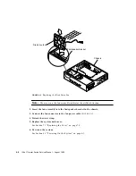
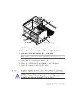
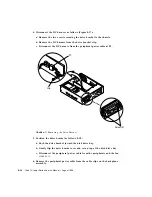
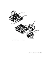
FIGURE 8-15
Removing the Backplane Assembly
7. Remove the two screws securing the backplane assembly to the bracket.
8. Disconnect the SCSI cable from J2602 on the system board.
Note –
J2602 is located between the disk drive bay and the system board.
9. Pull the SCSI cable out through the disk drive bay.
10. Remove the SCSI cable from the cable clips in the base of the chassis.
11. Remove the backplane assembly from the bracket.
8.5.2
Replacing the SCSI Cable/Backplane Assembly
Caution –
Use proper ESD grounding techniques when handling components. Wear
an antistatic wrist strap and use an ESD-protected mat. Store ESD-sensitive
components in antistatic bags before placing it on any surface.
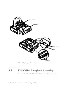
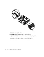
Cable
Clip (3)
SCSI cable
J2602
Backplane assembly
!
Summary of Contents for Ultra 1 Series
Page 8: ...viii Ultra 1 Creator Series Service Manual August 1996...
Page 21: ...Preface xxi Email smcc docs sun com Fax SMCC Document Feedback 1 415 786 6443...
Page 22: ...xxii Ultra 1 Creator Series Service Manual August 1996...
Page 34: ...2 4 Ultra 1 Creator Series Service Manual August 1996...
Page 70: ...6 4 Ultra 1 Creator Series Service Manual August 1996...
Page 110: ...8 36 Ultra 1 Creator Series Service Manual August 1996...
Page 126: ...9 16 Ultra 1 Creator Series Service Manual August 1996...
Page 158: ...10 32 Ultra 1 Creator Series Service Manual August 1996...
Page 164: ...A 4 Ultra 1 Creator Series Service Manual August 1996...
Page 186: ...B 22 Ultra 1 Creator Series Service Manual August 1996...
Page 208: ...C 22 Ultra 1 Creator Series Service Manual August 1996...
Page 212: ...Glossary 4 Ultra 1 Creator Series Service Manual August 1996...


