Chapter 1
Sun Ultra 20 M2 Workstation Hardware Features
1-3
1.2
Back Panel
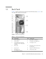
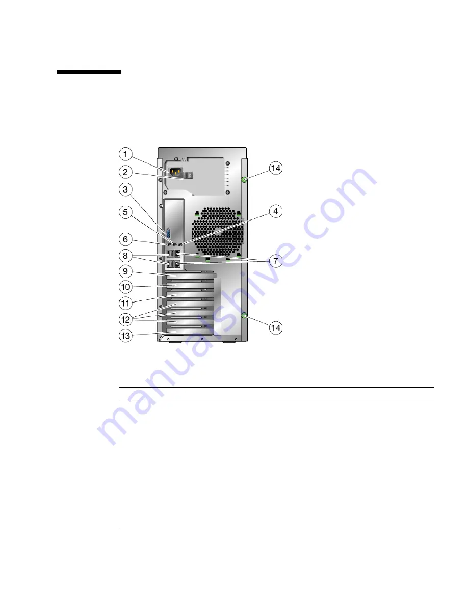
FIGURE 1-2
depicts the back panel of the Sun Ultra 20 M2 Workstation.
TABLE 1-2
lists
the components called out in the figure.
FIGURE 1-2
Back Panel Components
TABLE 1-2
Back Panel Components
Label
Connector/Slot
Label
Connector/Slot
1
Power connector
8
Four USB 2.0 connectors
2
Power switch
9
PCI Express x16 graphics slot
3
Onboard DB15 VGA graphics
connector (for ES 1000 graphics
controller)
10
PCI Express x1 slot
4
Line-in jack
11
PCI Express x16 mechanical slot
(x8 electrical)
5
Line-out jack
12
Three PCI 33-MHz 32-bit slots
6
Microphone jack
13
Cover plate, no slot
7
Two Ethernet connectors
Summary of Contents for Ultra 20 M2
Page 16: ...xvi Sun Ultra 20 M2 Workstation Service Manual January 2007...
Page 22: ...1 6 Sun Ultra 20 M2 Workstation Service Manual January 2007...
Page 30: ...2 8 Sun Ultra 20 M2 Workstation Service Manual January 2007...
Page 116: ...5 60 Sun Ultra 20 M2 Workstation Service Manual January 2007...
Page 132: ...B 10 Sun Ultra 20 M2 Workstation Service Manual January 2007...
Page 136: ...Index 4 Sun Ultra 20 M2 Workstation Service Manual January 2007...

