1-4
Sun Ultra 20 M2 Workstation Service Manual • January 2007
1.3
Internal Components and Cables
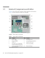
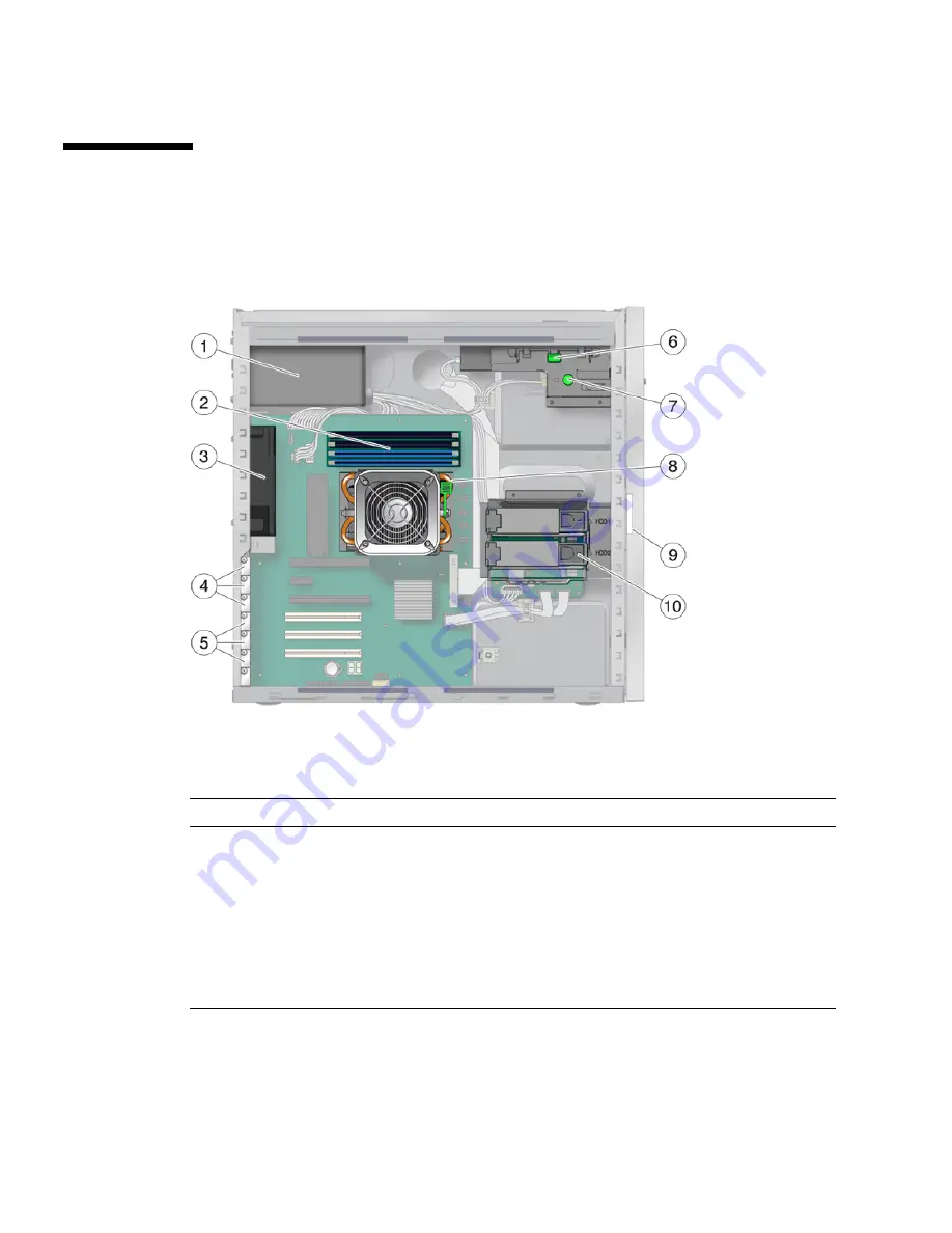
FIGURE 1-3
shows the location for major system components and connectors.
TABLE 1-3
lists the components called out in the figure.
FIGURE 1-3
Internal System Components
TABLE 1-3
Internal System Components
Label
Component
Label
Component
1
Power supply
6
DVD release lever
2
Memory (DIMMs)
7
I/O board release thumbscrew
3
System fan
8
Heatsink release lever
4
PCI Express slots (3) numbered
PCI-E slot 0 (top) to PCI-E slot 2
9
System serial number
5
PCI slots (3) numbered PCI slot 0
(top) to PCI slot 2
10
Hard disk drive(s)
Summary of Contents for Ultra 20 M2
Page 16: ...xvi Sun Ultra 20 M2 Workstation Service Manual January 2007...
Page 22: ...1 6 Sun Ultra 20 M2 Workstation Service Manual January 2007...
Page 30: ...2 8 Sun Ultra 20 M2 Workstation Service Manual January 2007...
Page 116: ...5 60 Sun Ultra 20 M2 Workstation Service Manual January 2007...
Page 132: ...B 10 Sun Ultra 20 M2 Workstation Service Manual January 2007...
Page 136: ...Index 4 Sun Ultra 20 M2 Workstation Service Manual January 2007...

