background image

Chapter 5

Maintaining the Workstation

5-5

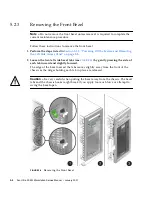
3. Gently move the left-front side of the bezel slightly to the left, then forward to

disengage the three chassis hooks on the right side (see

FIGURE 5-2

).

4. Remove the bezel and set it aside.

5.3

Closing the Workstation

This section describes how to install the left side access panel and the front bezel.

5.3.1

Postinstallation Instructions

Perform the following steps after installing a workstation component.

1. Ensure that all the components are installed as described in the step-by-step

instructions.

2. Reinstall any PCI cards, PCI-E cards, or peripherals that you removed.

3. Reinstall the system’s front bezel and left side access panel. See the following

sections:

Section 5.3.2, “Installing the Front Bezel” on page 5-5

.

Section 5.3.3, “Installing the Left Side Access Panel” on page 5-6

4. Connect all external cables to the system, then connect the AC power cord.

See

Section 2.3, “Connecting External Devices to the Workstation” on page 2-4

.

5. Power on the system.

See

Section 2.4, “Powering On the Workstation” on page 2-6

.

5.3.2

Installing the Front Bezel

Follow these steps to install the front bezel.

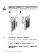
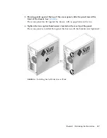
1. Insert the right side bezel hooks into the right side chassis slots. See

FIGURE 5-3

.

2. Insert the left side bezel tabs into the chassis slots, and gently press the left side

of the bezel toward the chassis until the tabs lock.

Summary of Contents for Ultra 20 M2

Page 1: ...Sun Microsystems Inc www sun com Submit comments about this document at http www sun com hwdocs feedback Sun Ultra 20 M2 Workstation Service Manual Part No 819 6584 11 January 2007 Revision A...

Page 2: ...icable provisions of the FAR and its supplements Copyright 2007 Sun Microsystems Inc 4150 Network Circle Santa Clara California 95054 Etats Unis Tous droits r serv s Sun Microsystems Inc d tient les d...

Page 3: ...stallation Process 2 2 2 2 Checking Package Contents 2 3 2 3 Connecting External Devices to the Workstation 2 4 2 4 Powering On the Workstation 2 6 2 5 Powering Off the Workstation 2 6 3 Troubleshooti...

Page 4: ...4 12 4 7 3 Accessing the Diagnostic Partition Under Red Hat Linux 4 13 4 7 4 Accessing the Diagnostic Partition Under the Solaris 10 Operating System 4 14 4 7 5 Accessing the Diagnostic Partition Unde...

Page 5: ...VD Drive 5 20 5 8 Removing or Installing DIMMs 5 22 5 8 1 Removing DIMMs 5 22 5 8 2 Installing DIMMs 5 23 5 8 3 Reconfiguring the System Memory 5 24 5 9 Removing and Installing a PCI E Card 5 25 5 9 1...

Page 6: ...cing the Motherboard 5 53 5 17 1 Removing the Motherboard 5 53 5 17 2 Installing the Motherboard 5 56 5 18 Updating the BIOS 5 58 5 18 1 Flashing the BIOS 5 58 5 18 2 Resetting Previous BIOS Settings...

Page 7: ...5 1 Removing the Side Access Panel 5 3 FIGURE 5 2 Removing the Front Bezel 5 4 FIGURE 5 3 Installing the Front Bezel 5 6 FIGURE 5 4 Installing the Left Side Access Panel 5 7 FIGURE 5 5 Removing a Har...

Page 8: ...ply Connections on the Motherboard 5 39 FIGURE 5 27 Removing the Power Supply From the Chassis 5 40 FIGURE 5 28 Installing the Power Supply Into the Chassis 5 41 FIGURE 5 29 Removing the I O Board Ass...

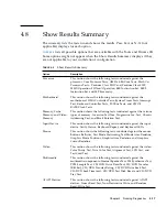
Page 9: ...ation Menu Options 4 3 TABLE 4 2 Advanced Diagnostics Tests Menu Options 4 4 TABLE 4 3 Parameters for the HDD Tests 4 7 TABLE 4 4 Continuous Burn in Testing Options 4 8 TABLE 4 5 Show Results Summary...

Page 10: ...x Sun Ultra 20 M2 Workstation Service Manual January 2007 TABLE A 7 Input Current A 5 TABLE A 8 Sun Ultra 20 M2 Workstation Environmental Specifications A 6 TABLE B 1 BIOS Port 80 POST Codes B 2...

Page 11: ...nd software How this Document is Organized Chapter 1 provides an overview of the Sun Ultra 20 M2 Workstation Chapter 2 describes how to connect external cables and power on or off the workstation Chap...

Page 12: ...s Meaning Examples AaBbCc123 The names of commands files and directories on screen computer output Edit your login file Use ls a to list all files You have mail AaBbCc123 What you type when contrasted...

Page 13: ...man Italian Japanese Korean and Spanish English documentation is revised more frequently and might be more up to date than the translated documentation Documentation Warranty Support and Training URLs...

Page 14: ...third party web sites mentioned in this document Sun does not endorse and is not responsible or liable for any content advertising products or other materials that are available on or through such sit...

Page 15: ...its documentation and welcomes your comments and suggestions You can submit your comments by going to http www sun com hwdocs feedback Please include the title and part number of your document with y...

Page 16: ...xvi Sun Ultra 20 M2 Workstation Service Manual January 2007...

Page 17: ...atures This chapter provides an overview of the Sun Ultra 20 M2 Workstation hardware features and includes the following sections Section 1 1 Front Panel on page 1 2 Section 1 2 Back Panel on page 1 3...

Page 18: ...nel of the Sun Ultra 20 M2 Workstation TABLE 1 1 lists the components called out in the figure FIGURE 1 1 Front Panel Components TABLE 1 1 Front Panel Components Label Button LED Port Label Button LED...

Page 19: ...BLE 1 2 Back Panel Components Label Connector Slot Label Connector Slot 1 Power connector 8 Four USB 2 0 connectors 2 Power switch 9 PCI Express x16 graphics slot 3 Onboard DB15 VGA graphics connector...

Page 20: ...out in the figure FIGURE 1 3 Internal System Components TABLE 1 3 Internal System Components Label Component Label Component 1 Power supply 6 DVD release lever 2 Memory DIMMs 7 I O board release thum...

Page 21: ...e Connection 1 Power supply 3 to DVD drive 8 DVD drive to motherboard IDE 2 DVD drive analog to motherboard J8 9 I O board J5 to motherboard USB 3 3 I O board J1 to motherboard J7 10 Storage backplane...

Page 22: ...1 6 Sun Ultra 20 M2 Workstation Service Manual January 2007...
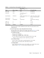
Page 23: ...2 Workstation on and off The chapter includes the following sections Section 2 1 Planning the Installation Process on page 2 2 Section 2 2 Checking Package Contents on page 2 3 Section 2 3 Connecting...

Page 24: ...er 2 See Section 2 4 Powering On the Workstation on page 2 6 See the Sun Ultra 20 M2 Workstation Installation Guide Install your OS To install an optional supported OS see the Sun Ultra 20 M2 Workstat...

Page 25: ...20 M2 Workstation Box Hardware Sun Ultra 20 M2 Workstation DMS 59 cable if the workstation is configured with an NVS285 graphics card Documentation Depending on the system configuration ordered some s...

Page 26: ...ect external devices to the workstation 1 Connect the workstation power cord to a grounded electrical outlet 2 Connect the keyboard to a USB connector on the back or front panel 3 Connect the mouse to...

Page 27: ...r to the onboard video connector See the top of FIGURE 2 3 If a PCI Express graphics card is installed in the top PCI E slot connect the monitor to the graphics card connector See the bottom of FIGURE...

Page 28: ...Caution Be careful when making changes to the system BIOS as some changes can cause your system to malfunction 2 5 Powering Off the Workstation 1 Save your data and close any open applications 2 Read...

Page 29: ...ltra 20 M2 Workstation 2 7 If the proceeding options do not power off the workstation turn the power switch on the back panel to the Off 0 position After powering off the workstation wait at least fou...

Page 30: ...2 8 Sun Ultra 20 M2 Workstation Service Manual January 2007...

Page 31: ...ific workstation problem collect the following information What events occurred prior to the failure Was any hardware or software modified or installed Was the workstation recently installed or moved...

Page 32: ...ng an External Visual Inspection 1 Turn off the system and any attached peripherals if applicable 2 Verify that all power cables are properly connected to the system the monitor and peripherals and ch...

Page 33: ...ide access panel 8 Reconnect the system and any attached peripherals to their power sources and then power them on 3 3 Troubleshooting Procedures TABLE 3 1 contains possible problems that might arise...

Page 34: ...rd See Appendix B for detailed information on the POST codes Workstation powers on but the monitor does not Is the Power button for the monitor turned on Is the monitor power cord connected to a wall...

Page 35: ...place the left side access panel 5 Turn on the workstation CD or DVD does not eject from the media tray when you press the Eject button Move the mouse or press any key on the keyboard The drive might...

Page 36: ...rom a terminal window type ping hostname 2 If there is no response remotely log in from another system using telnet or rlogin and ping the system again 3 Attempt to kill processes until the system res...

Page 37: ...ting another device Is the video card seated correctly in its connector Are the internal cables properly connected to the video card Does the monitor work when connected to another system If you have...

Page 38: ...s full search capabilities http docs sun com documentation Discussion and troubleshooting forums http supportforum sun com Support diagnostic tools and alerts for all Sun products http www sun com big...

Page 39: ...iagnostic scripts for the Sun Ultra 20 M2 Workstation The following sections describe how to start and use the diagnostics and provide detailed descriptions of menu items and tests Section 4 1 Underst...

Page 40: ...r workstation must be running a Sun supported Linux or Solaris OS Refer to the Sun Ultra 20 M2 Workstation Operating System Installation Guide for a list of supported operating systems You must access...

Page 41: ...eate a document showing information about your system including comparisons between the updates and the newest versions of your system XML is the format used to create and display this information tho...

Page 42: ...ocessor speed CMOS RAM Utilities Shows the CMOS settings of the system SCSI Utilities Not applicable for the Sun Ultra 20 M2 Workstation Text File Editor Opens a text editor Start Up Options Enables y...

Page 43: ...on about FireWire devices and includes a FireWire tests menu Network Performs network register controller tests Keyboard Includes a Keyboard Test menu with options for performing different tests on th...

Page 44: ...menu displays the following options Select Drive Test Settings Read Test Read Verify Test Non Destructive Write Test Destructive Write Test Mechanics Stress Test Internal Cache Test View Error Log Ut...

Page 45: ...o test and the sectors to be tested on the hard disk Device Test Settings Enables you to select the test time durations of the devices and the test level Number of Retries Enables you to select the nu...

Page 46: ...components including those components which require user input This script contains a more in depth memory test than quick tst as well as external port tests which might require loopback connectors Y...

Page 47: ...e d testname tst Where testname is the name of the script that you created Change Options Opens the Burn in Options menu which enables you to modify the various options listed in TABLE 4 4 for the cur...

Page 48: ...ribed in TABLE 4 4 and the bottom portion of the window lists the following Burn in menu options Load Burn in Script Type one of the following quick tst noinput tst or full tst If you created and save...

Page 49: ...station Section 4 7 1 Adding a Diagnostic Partition to the First Bootable Disk on page 4 11 Section 4 7 2 Creating a Log File on the Diagnostic Partition on page 4 12 Section 4 7 3 Accessing the Diagn...

Page 50: ...the scripts that are loadable with the hardware diagnostics software are predefined with logging to the diagnostic partition enabled The names of log files correspond to the name of the script For ex...

Page 51: ...e superuser 4 To determine whether your diagnostic partition is configured to be mounted type the following command If this command does not list the log files created by the hardware diagnostics soft...

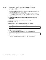
Page 52: ...0 Type the following command The contents of the diagnostic partition are listed 4 7 4 Accessing the Diagnostic Partition Under the Solaris 10 Operating System Perform this procedure to access the dia...

Page 53: ...users have read access to this partition Only the superuser has read write access to this partition You do not need to continue this procedure 5 Insert the Tools and Drivers CD into the DVD drive tra...

Page 54: ...Ultra 20 M2 Workstation and complete the following procedure 1 Connect the USB diskette drive to any USB port on the Sun Ultra 20 M2 Workstation 2 Insert the Tools and Drivers CD into the DVD drive t...

Page 55: ...Video Memory This section shows the following tests conducted against the various types of memory Inversion Test Tree Progressive Inv Test Chaotic Addressing Test and Block Rotation Test Input Device...

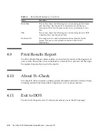
Page 56: ...mponents such as mouse devices 4 11 Exit to DOS The Exit to DOS option exits Pc Check and returns you to the DOS prompt Hard Disk This section shows the following tests conducted against the hard disk...

Page 57: ...12 Section 5 6 Replacing the Storage Backplane on page 5 15 Section 5 7 Replacing the DVD Drive on page 5 19 Section 5 8 Removing or Installing DIMMs on page 5 22 Section 5 9 Removing and Installing...

Page 58: ...ear a wrist strap and attach it to the system chassis ground or to any metal part of the system before handling components Turn off the power switch on the back of the chassis Caution Do not operate t...

Page 59: ...off the system before you start installing components can cause serious component damage 3 To maintain system grounding do not unplug the AC power cord from the back of the system unless the specific...

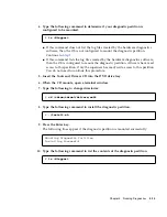
Page 60: ...moving the Left Side Access Panel on page 5 3 2 Loosen the two left side bezel tabs see FIGURE 5 2 by gently pressing the side of each tab inward and slightly forward The edge of the bezel nearest the...

Page 61: ...ds or peripherals that you removed 3 Reinstall the system s front bezel and left side access panel See the following sections Section 5 3 2 Installing the Front Bezel on page 5 5 Section 5 3 3 Install...

Page 62: ...nstalling the Left Side Access Panel Install the left side access panel after you finish inspecting or installing components 1 Ensure that all of the components are installed as described in the step...

Page 63: ...front of the chassis See FIGURE 5 4 The access panel lies flat against the chassis with no gaps between the two 6 Tighten the two captive thumbscrews located on the rear lip of the panel The access p...

Page 64: ...s located beneath the HDD cage When correctly inserted into the HDD cage the HDD makes contact with the connectors on the storage backplane The storage backplane also has cables linking it to the powe...

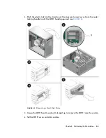
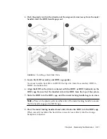
Page 65: ...the direction of the engraved arrow away from the metal locking handle until the HDD handle pops out see FIGURE 5 5 FIGURE 5 5 Removing a Hard Disk Drive 5 Grasp the HDD handle and pull straight up to...

Page 66: ...rforming the steps in Section 5 3 1 Postinstallation Instructions on page 5 5 5 4 2 Installing a Hard Disk Drive Perform this procedure to install an HDD 1 Perform the steps listed in Section 5 2 2 Po...

Page 67: ...ot 6 Align the HDD so the drive is centered with the HDD1 or HDD2 indicator on the HDD cage Be sure that the labelled side of the HDD faces the top of the system 7 Slide the HDD into the HDD cage unti...

Page 68: ...s panel See Section 5 2 2 Powering Off the System and Removing the Left Side Access Panel on page 5 3 2 Remove the SATA HDDs from the drive bay See Section 5 4 1 Removing a Hard Disk Drive on page 5 8...

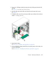
Page 69: ...and secure the card with a screw See FIGURE 5 7 7 To keep the cables out of the air stream carefully resecure them in the tie downs FIGURE 5 7 Installing a SAS Card 8 Install the SAS drives See Secti...

Page 70: ...SAS configuration Refer to the Sun Ultra 20 M2 Workstation Operating System Installation Guide at http www sun com products n solutions hardware docs Workstation_Products Workstations ultra_20m2 inde...

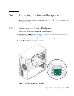
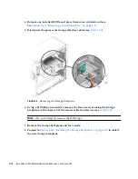
Page 71: ...emoving or Adding a Hard Disk Drive on page 5 8 5 6 1 Removing the Storage Backplane Perform this procedure to remove the storage backplane 1 Follow the instructions in Section 5 2 2 Powering Off the...

Page 72: ...erface cables see FIGURE 5 9 FIGURE 5 9 Removing the Storage Backplane 6 Using a 2 Phillips screwdriver remove the four screws securing the storage backplane to the chassis Set the screws aside for la...

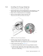
Page 73: ...ition the screw holes over the holes in the chassis FIGURE 5 10 Installing the Storage Backplane 4 Fasten the storage backplane to the hard drive cage Using a 2 Phillips screwdriver install the four s...

Page 74: ...a Hard Disk Drive on page 5 10 7 Inspect the storage backplane cables and installed HDDs Be sure that the power cable is seated in the storage backplane Be sure that the storage interface cables are s...

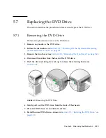
Page 75: ...System and Removing the Left Side Access Panel on page 5 3 3 Remove the front bezel see Section 5 2 3 Removing the Front Bezel on page 5 4 4 Disconnect the cables from the back of the DVD drive 5 Push...

Page 76: ...the Left Side Access Panel on page 5 3 2 Remove the new DVD drive from its packaging 3 Lifting the front end slightly slide the 5 25 inch DVD drive into the drive bay until the holes on the side align...

Page 77: ...3 Refer to the cabling diagram in the service label on the side of the chassis for information on correct cable routing FIGURE 5 13 Location of Power and IDE Cables 7 Replace the front bezel and left...

Page 78: ...ESD precautions when changing DIMMs see Section 5 1 Electrostatic Discharge ESD Precautions on page 5 2 5 8 1 Removing DIMMs Perform this procedure to remove a DIMM 1 Follow the instructions in Secti...

Page 79: ...ation keep the following guidelines in mind Memory modules must be installed and removed in pairs observing sequential slot positions DIMM slots are numbered 0 to 3 Slot 0 is closest to the CPU Popula...

Page 80: ...locked into place The DIMM is seated when you hear a click and the DIMM ejector levers are in the vertical position FIGURE 5 16 Installing a DIMM 6 Repeat Step 3 through Step 5 for each DIMM that you...

Page 81: ...ds on page 5 29 5 9 1 Removing a PCI E Card Perform this procedure to remove a PCI E card 1 Perform the steps listed in Section 5 2 2 Powering Off the System and Removing the Left Side Access Panel on...

Page 82: ...forward and then lift it straight out of the card slot and set it aside on an antistatic surface 6 Choose your next step If you are replacing the card follow the instructions in Section 5 9 2 Install...

Page 83: ...s right side on a stable nonslip surface 3 Refer to the service label on the inside of the access panel to help you choose an empty card slot that is compatible with the card that you are installing 4...

Page 84: ...Manual January 2007 8 If you are installing an NVIDIA FX3500 graphics card connect the graphics power cable to the connector on the card This might require moving the cable out of its cable tie FIGUR...

Page 85: ...0 Removing and Installing PCI Cards This section describes removing and installing standard PCI cards To remove and replace PCI E cards see Section 5 9 Removing and Installing a PCI E Card on page 5 2...

Page 86: ...et it aside on an antistatic surface FIGURE 5 19 Removing a PCI Card 6 Choose your next step If you are not replacing the PCI card replace the slot filler panel then close the system by performing the...

Page 87: ...les on page 1 4 for PCI slot locations and to Section A 3 PCI E and PCI Expansion Slots on page A 4 for slot specifications 1 Perform the steps listed in Section 5 2 2 Powering Off the System and Remo...

Page 88: ...ot see FIGURE 5 20 FIGURE 5 20 Installing a PCI card 7 Press down on the card until it is completely seated in the slot 8 Fasten the retaining screw into place Torque the screws to 8 to 9 inch pounds...

Page 89: ...u could erase all system specific information saved in the CMOS 1 Perform the steps listed in Section 5 2 2 Powering Off the System and Removing the Left Side Access Panel on page 5 3 2 Gently lay the...

Page 90: ...5 34 Sun Ultra 20 M2 Workstation Service Manual January 2007 4 Lift the battery to remove it see FIGURE 5 21 FIGURE 5 21 Removing the System Battery...

Page 91: ...up see FIGURE 5 22 Tilt the battery into the battery connector angling the battery under the battery latch Slide the battery until it clicks into place FIGURE 5 22 Installing a System Battery 6 Close...

Page 92: ...connector on the motherboard To locate the SYS_FAN connector refer to the Service Label on the left side access panel or to Section 1 3 Internal Components and Cables on page 1 4 4 Release the fan s...

Page 93: ...ner holes on the chassis grill 11 Slide the fan up until the latches click into their locked position see FIGURE 5 24 FIGURE 5 24 Installing the System Fan 12 Route the fan s power cord through the ca...

Page 94: ...he Power Supply Perform this procedure to remove the power supply 1 Follow the steps in Section 5 2 2 Powering Off the System and Removing the Left Side Access Panel on page 5 3 2 Unplug the AC power...

Page 95: ...o the motherboard DVD drive and storage backplane see FIGURE 5 26 and TABLE 5 2 FIGURE 5 26 Locations of Power Supply Connections on the Motherboard 7 Working from outside the back of the chassis unfa...

Page 96: ...January 2007 8 Remove the power supply from the interior of the system chassis see FIGURE 5 27 FIGURE 5 27 Removing the Power Supply From the Chassis 9 Install the new power supply as shown as Section...

Page 97: ...the power supply IEC 320 connector power cord socket and fan with the chassis back panel opening b Position the power supply with the chassis power supply brackets c Rotate the power supply down and...

Page 98: ...s on page 5 5 5 14 Replacing the I O Board Assembly The I O board assembly sits beneath the DVD drive and contains the power switch power LED and external connectors for the front panel 5 14 1 Removin...

Page 99: ...rew securing the I O board to the metal frame see FIGURE 5 29 FIGURE 5 29 Removing the I O Board Assembly 7 Push the I O board out the front of the chassis 8 Install the new I O board assembly as show...

Page 100: ...sh with the bezel opening see FIGURE 5 30 Wiggle side to side if the board binds as you install it FIGURE 5 30 Installing the I O Board Assembly 4 Tighten the captive screw on the metal I O board fram...

Page 101: ...io cable HDD cables Each cable connector on the motherboard is labeled to help you identify the cable to which it should be connected Perform this procedure to remove and install system cables 1 Perfo...

Page 102: ...m this procedure to remove the heatsink and CPU Note Before removing the CPU from the motherboard create a backup file to preserve all important data 1 Follow the steps in Section 5 2 2 Powering Off t...

Page 103: ...e hook on the retaining bracket see FIGURE 5 31 FIGURE 5 31 Unlatching the Heatsink Fan Assembly 5 Push down the metal latch on the left side of the assembly to loosen the latch from the hook on the r...

Page 104: ...he heatsink fan assembly straight up and withdraw it from the board see FIGURE 5 32 FIGURE 5 32 Removing the Heatsink Fan Assembly From the Motherboard 8 Place the heatsink upside down on a flat surfa...

Page 105: ...stalling a Heatsink and CPU on page 5 49 5 16 2 Installing a Heatsink and CPU Perform this procedure to install the heatsink and CPU Note Observe the ESD precautions and preinstallation procedures des...

Page 106: ...tsink assembly already has thermal grease applied You do not need to apply additional thermal grease b Remove the plastic cover from the heatsink fan assembly 6 Do this step if you are installing an a...

Page 107: ...e performance of the thermal grease 7 Inspect the heatsink fan assembly for dust and lint Clean if necessary 8 Carefully position the heatsink fan assembly on the CPU aligning it with the mounting hoo...

Page 108: ...et hook to the metal latch on the left side of the heatsink fan assembly see FIGURE 5 36 FIGURE 5 36 Securing the Heatsink Fan Assembly Latches 10 Push down on the lever on the right side of the heats...

Page 109: ...ians 5 17 1 Removing the Motherboard Perform this procedure to remove the motherboard 1 Follow the steps in Section 5 2 2 Powering Off the System and Removing the Left Side Access Panel on page 5 3 2...

Page 110: ...y 2007 6 Remove the nine Phillips screws that fasten the motherboard to the chassis see FIGURE 5 37 FIGURE 5 37 Removing the Nine Motherboard Screws Note Do not remove the four screws that secure the...

Page 111: ...from the chassis see FIGURE 5 38 FIGURE 5 38 Removing the Motherboard From the Chassis Refer to the following sections to remove and replace the CPU and memory Section 5 16 Replacing the Heatsink and...

Page 112: ...ge 5 22 2 Place the motherboard on the chassis so that the screw holes in the motherboard align with the screw holes on the chassis 3 Secure the nine Phillips screws that fasten the motherboard to the...

Page 113: ...Chapter 5 Maintaining the Workstation 5 57 7 Close the system by performing the steps in Section 5 3 1 Postinstallation Instructions on page 5 5 FIGURE 5 39 Installing the Motherboard...

Page 114: ...ironment because flashing the BIOS will restore the default BIOS settings 2 Download the latest Sun Ultra 20 M2 Workstation Tools and Drivers CD ISO image from the Sun web site http www sun com downlo...

Page 115: ...he system 2 Press the F2 key to enter the BIOS configuration The BIOS Setup screen displays 3 Make any setting changes you require In particular ensure that RAID settings are enabled if required and s...

Page 116: ...5 60 Sun Ultra 20 M2 Workstation Service Manual January 2007...
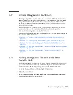
Page 117: ...ion A 2 Memory Configurations on page A 3 Section A 3 PCI E and PCI Expansion Slots on page A 4 Section A 4 Physical Specifications on page A 4 Section A 5 Power Specifications on page A 5 Section A 6...

Page 118: ...o two SATA disk drives Power supply 400W PSU Network I O Onboard 10 100 1000BASE T Gigabit Ethernet controller providing 2 RJ45 connectors on the back panel Video Onboard ATI graphics controller with...

Page 119: ...DIMM kits at http store sun com DIMM slots are numbered from DIMM 0 to DIMM 3 Populate DIMM slots starting farthest from the CPU that is starting with slot 3 TABLE A 2 Sun Ultra 20 M2 Workstation Memo...

Page 120: ...Not for graphics accelerators Intended for PCI Express expansion cards such as NIC Middle 2 PCI Express x16 mechanical x8 electrical x16 Full Not for graphics accelerators Intended for PCI Express exp...

Page 121: ...packaging 34 lb 15 4 kg TABLE A 5 Input Voltage Range Input Voltage Minimum Nominal Maximum Units Range 1 90 115 132 Vrms Range 2 180 230 264 Vrms TABLE A 6 Input Frequency Range Input Frequency Minim...

Page 122: ...7 93 RH noncondensing 38 C max wet bulb Nonoperating 93 RH noncondensing 109 4 F max wet bulb 93 RH noncondensing 43 C max wet bulb Vibration Operating 0 25G in all axes 5 500 Hz sine Nonoperating 1 2...

Page 123: ...are or configuration errors However if the error is so severe that the BIOS halts immediately or cannot initialize the video you can read the last executed POST code from the port 80 LED The port 80 L...

Page 124: ...codes locating in physical address 1000 0 02h Reserved 03h Initial Superio_Early_Init switch 04h Reserved 05h 1 Blank out screen 2 Clear CMOS error flag 06h Reserved 07h 1 Clear 8042 interface 2 Init...

Page 125: ...g brand SMI type Cyrix or Intel and CPU level 586 or 686 19h Reserved 1Ah Reserved 1Bh Initial interrupts vector table If no special specified all hardware interrupts are directed to SPURIOUS_INT_HDLR...

Page 126: ...P6 and PII for 0 640K memory address 2 Initialize the APIC for Pentium class CPU 3 Program early chipset according to CMOS setup Example onboard IDE controller 4 Measure CPU speed 2Ah Reserved 2Bh Inv...

Page 127: ...h 1 Calculate total memory by testing the last double word of each 64K page 2 Program write allocation for AMD K5 CPU 4Ah Reserved 4Bh Reserved 4Ch Reserved 4Dh Reserved 4Eh 1 Program MTRR of M1 CPU 2...

Page 128: ...rus code 5Ah Reserved 5Bh Optional feature Show message for entering AWDFLASH EXE from FDD 5Ch Reserved 5Dh 1 Initialize Init_Onboard_Super_IO 2 Initialize Init_Onbaord_AUDIO 5Eh Reserved 5Fh Reserved...

Page 129: ...ed 75h Detect and install all IDE devices HDD LS120 ZIP CD ROM and so on 76h Optional Feature Enter AWDFLASH EXE if AWDFLASH EXE is found on diskette drive ALT F2 is pressed 77h Detect serial ports an...

Page 130: ...up ACPI table at top of the memory 8Ah Reserved 8Bh 1 Invoke all ISA adapter ROMs 2 Invoke all PCI ROMs except VGA 8Ch Reserved 8Dh 1 Enable disable parity check according to CMOS setup 2 APM initial...

Page 131: ...and typematic rate 96h 1 Build MP table 2 Build and update ESCD 3 Set CMOS century to 20h or 19h 4 Load CMOS time into DOS timer tick 5 Build MSIRQ routing table FFh Boot attempt INT 19h TABLE B 1 BI...

Page 132: ...B 10 Sun Ultra 20 M2 Workstation Service Manual January 2007...

Page 133: ...locating 1 5 replacing 5 45 components access panel installing 5 6 removing 5 3 battery 5 33 bezel installing 5 5 removing 5 4 cables locating 1 5 replacing 5 45 connecting external 2 4 front panel 1...

Page 134: ...5 5 45 heatsink and CPU installing 5 49 removing 5 46 I I O board assembly front panel view 1 2 installing 5 44 removing 5 42 IDE 5 45 IEEE 1394 5 45 A 2 installation bezel removal 5 4 5 5 opening the...

Page 135: ...cifications environmental A 6 physical A 4 power A 5 storage backplane replacing 5 15 to 5 18 support obtaining 3 8 system components and features A 2 system serial number 1 4 system setup flowchart 2...

Page 136: ...Index 4 Sun Ultra 20 M2 Workstation Service Manual January 2007...
Reviews: