vii
Figures
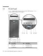
FIGURE 1-1
Front Panel Components
1–2
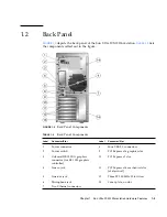
FIGURE 1-2
Back Panel Components
1–3
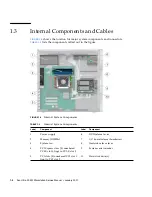
FIGURE 1-3
Internal System Components
1–4
FIGURE 1-4
Power Supply and Component Cable Connections to Motherboard
1–5
FIGURE 2-1
Process Flow for Setting Up the Sun Ultra 20 M2 Workstation
2–2
FIGURE 2-2
External Cable Connections
2–4
FIGURE 2-3
Connecting the Monitor to the System
2–5
FIGURE 5-1
Removing the Side Access Panel
5–3
FIGURE 5-2
Removing the Front Bezel
5–4
FIGURE 5-3
Installing the Front Bezel
5–6
FIGURE 5-4
Installing the Left Side Access Panel
5–7
FIGURE 5-5
Removing a Hard Disk Drive
5–9
FIGURE 5-6
Installing a Hard Disk Drive
5–11
FIGURE 5-7
Installing a SAS Card
5–13
FIGURE 5-8
Location of the Storage Backplane
5–15
FIGURE 5-9
Removing the Storage Backplane
5–16
FIGURE 5-10
Installing the Storage Backplane
5–17
FIGURE 5-11
Removing the DVD Drive
5–19
FIGURE 5-12
Installing the DVD Drive
5–20
FIGURE 5-13
Location of Power and IDE Cables
5–21
Summary of Contents for Ultra 20 M2
Page 16: ...xvi Sun Ultra 20 M2 Workstation Service Manual January 2007...
Page 22: ...1 6 Sun Ultra 20 M2 Workstation Service Manual January 2007...
Page 30: ...2 8 Sun Ultra 20 M2 Workstation Service Manual January 2007...
Page 116: ...5 60 Sun Ultra 20 M2 Workstation Service Manual January 2007...
Page 132: ...B 10 Sun Ultra 20 M2 Workstation Service Manual January 2007...
Page 136: ...Index 4 Sun Ultra 20 M2 Workstation Service Manual January 2007...


