Chapter 5
Maintaining the Workstation
5-29
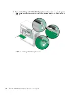
9. Fasten the retaining screw into place. Torque the screws to 8- to 9-inch pounds.
10. Close the system by performing the steps in
Section 5.3.1, “Postinstallation
Instructions” on page 5-5
.
Note –
The onboard ATI graphics controller automatically stops working when you
install a graphics card into the PCI-E x16 slot (PCI-E slot 0). Therefore, a monitor
connected to the onboard DB15 VGA graphics connector will not provide any
output.
5.10
Removing and Installing PCI Cards
This section describes removing and installing standard PCI cards.
To remove and replace PCI-E cards, see
Section 5.9, “Removing and Installing a PCI-
E Card” on page 5-25
.
5.10.1
Removing a PCI Card
This procedure describes how to remove a typical PCI card (including a host bus
adapter). PCI cards might vary in the way in they are installed in the system.
1. Perform the steps listed in
Section 5.2.2, “Powering Off the System and Removing
the Left Side Access Panel” on page 5-3
.
2. Gently lay the system on its right side on a stable, nonslip surface.
3. Remove any cables connected to the card.
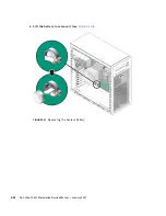
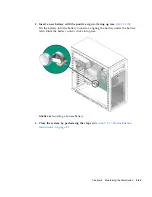
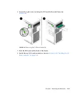
4. Unscrew the PCI card retainer screw
(see
FIGURE 5-19
)
.
Summary of Contents for Ultra 20 M2
Page 16: ...xvi Sun Ultra 20 M2 Workstation Service Manual January 2007...
Page 22: ...1 6 Sun Ultra 20 M2 Workstation Service Manual January 2007...
Page 30: ...2 8 Sun Ultra 20 M2 Workstation Service Manual January 2007...
Page 116: ...5 60 Sun Ultra 20 M2 Workstation Service Manual January 2007...
Page 132: ...B 10 Sun Ultra 20 M2 Workstation Service Manual January 2007...
Page 136: ...Index 4 Sun Ultra 20 M2 Workstation Service Manual January 2007...

