Chapter 1
System Setup
5
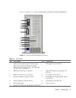
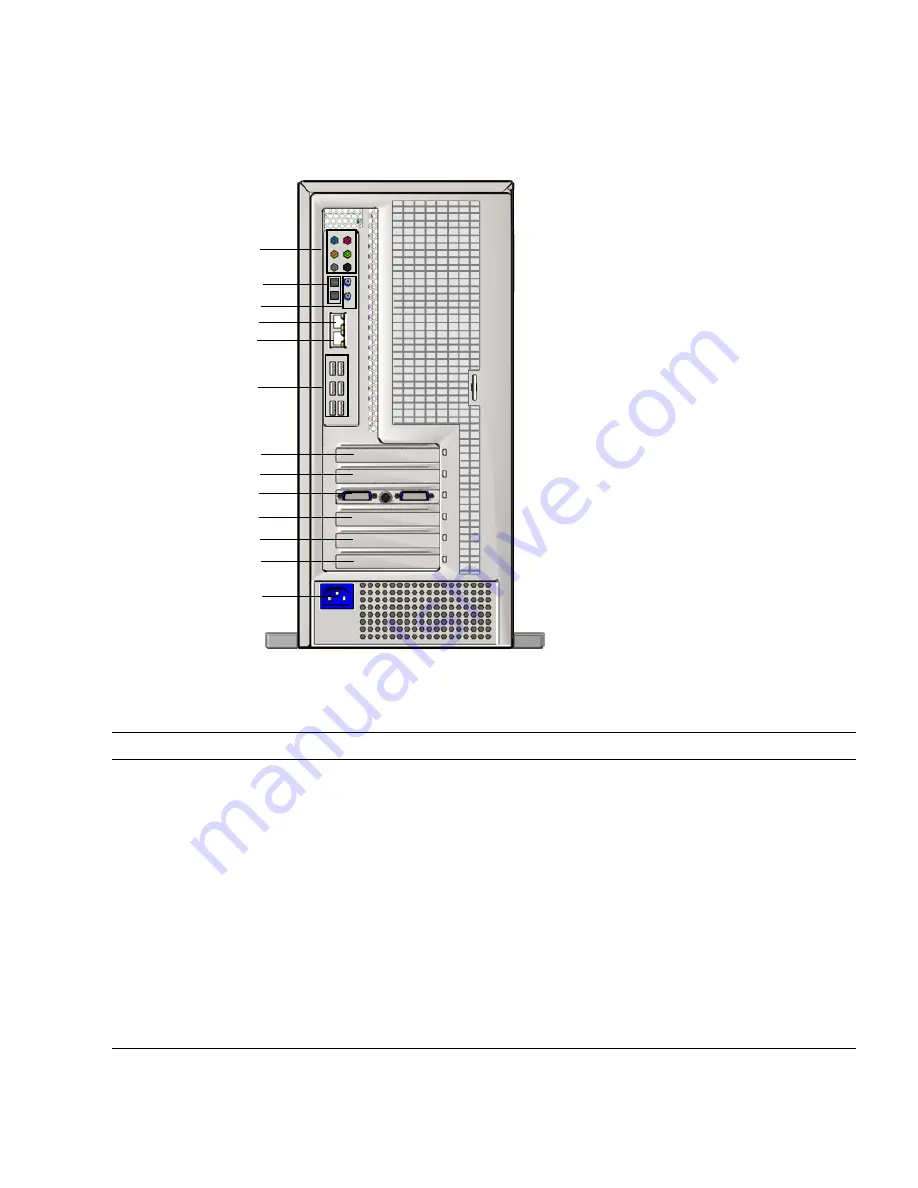
FIGURE 1-4
and
TABLE 1-2
show the back panel of the Sun Ultra 40 Workstation.
FIGURE 1-4
Sun Ultra 40 Workstation Back Panel
TABLE 1-2
Back Panel
Label
Connector/Slot
Label
Connector/Slot
1
Audio connectors (6) top left to bottom right:
Blue: line in; Pink: microphone-in; Orange:
center/LFE; Lime: line-out; Gray: side surround
out; Black: back surround out
8
PCI-Express x4 slot (PCI-E 2)
2
SPDIF optical (out top, in, bottom)
9
Primary PCI-Express x16 graphics slot
(PCI-E 1)
3
SPDIF coaxial (out top, in, bottom)
10
PCI 33 MHz/32-bit (PCI 1)
4
Secondary Ethernet connector (NIC1)
11
PCI 33 MHz/32-bit (fits 66 MHz/64-bit
card) (PCI 0)
5
Primary Ethernet connector (NIC0)
12
PCI-Express x4 slot (PCI-E 0)
6
USB connectors (6)
13
Power connector
7
Secondary PCI-Express x16 graphics slot (PCI-E 3)
1
2
3
5
10
4
7
6
8
9
11
12
13

