12
TECHNICAL PASSPORT. INSTALLATION and OPERATION MANUAL
TECHNICAL PASSPORT. INSTALLATION and OPERATION MANUAL
TECHNICAL PASSPORT. INSTALLATION and OPERATION MANUAL
TECHNICAL PASSPORT. INSTALLATION and OPERATION MANUAL
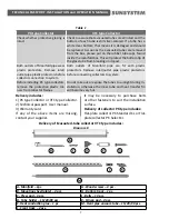
Diagram
19
Once you have installed the
framework and the manifold, put
the system together and check its
integrity and correct function. If no
leaks are detected, you can install
the evacuated tubes.
E
M
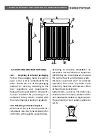
Diagram 20
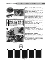
Step 4.
Take the plastic tube hangers D.
Their number is equal to the number of
pipes. Place them in the holes on the
bottom rail H. /Diagram 20/
Step 5.
Carefully take evacuated tube M
out of the box. The upper end of the tube
with a silver probe-like tip as must fit in
the manifold nest. The lower end of the
tube must pass through tube holder D.
Place the plastic protector on the bottom
of tube M. Carefully screw the protector
onto the holder.
Repeat this until you install all glass
evacuated tubes M
.
/Diagram 20/
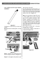
6.2.3. Installation of VTC type evacuated
tube collectors on façade
Installation should be carried out by
at least two people. We recommend
consulting with a carrier wall expert.
6.3.
Collector array connection
For connecting several collectors in
array, it is necessary to use the flexible
pipes between two collectors because
of material expansion upon heating and
contraction upon cooling.
D
Diagram 21


